Cutting fluid waste oil clearing device

A technology for removing device and cutting fluid, which is applied in the direction of liquid separation, maintenance and safety accessories, manufacturing tools, etc. It can solve the problems of oil collection port deviation from waste oil, unstable work, accumulation, etc., and achieve high removal efficiency and stable work Effect

Pending Publication Date: 2018-11-23
逸乐(廊坊)环保科技有限公司
View PDF0 Cites 2 Cited by
  • Summary
  • Abstract
  • Description
  • Claims
  • Application Information

AI Technical Summary

Problems solved by technology

In the process of changing and cleaning the cutting fluid, the production line of the enterprise needs to be shut down, which will reduce the production efficiency of the enterprise. In addition, the enterprise also needs to hire workers to clean and change the fluid, and needs to pay labor costs. The combination of the two makes the maintenance cost of the enterprise constantly stay high
[0003] At present, some enterprises add waste oil collection devices to the cutting fluid circulation system, most of which use floating skins to collect waste oil. The collected floating oil flows into the interior along the skins, and then is transported to the corresponding processor by pipelines. The production cost is high, because the waste oil flows through the inner wall of the skin bag, causing grease or dirt to accumulate on the inner wall of the skin bag, causing the oil inlet to fluctuate up and down due to the change of buoyancy, the work is unstable, the waste oil is not cleaned thoroughly, and the inside of the bag needs to be cleaned frequently, and the production cost It is also relatively high, and there is no guiding device for floating up and down, and it is easy to overturn under the action of suction, so someone must be guarded when working. The oil port deviates from the waste oil (slick oil layer), which leads to unsatisfactory collection of waste oil by the device

Method used


Image

  • Cutting fluid waste oil clearing device
  • Cutting fluid waste oil clearing device
  • Cutting fluid waste oil clearing device

Examples


Embodiment Construction

[0028] The present invention will be further described in detail below in conjunction with the accompanying drawings and specific embodiments.

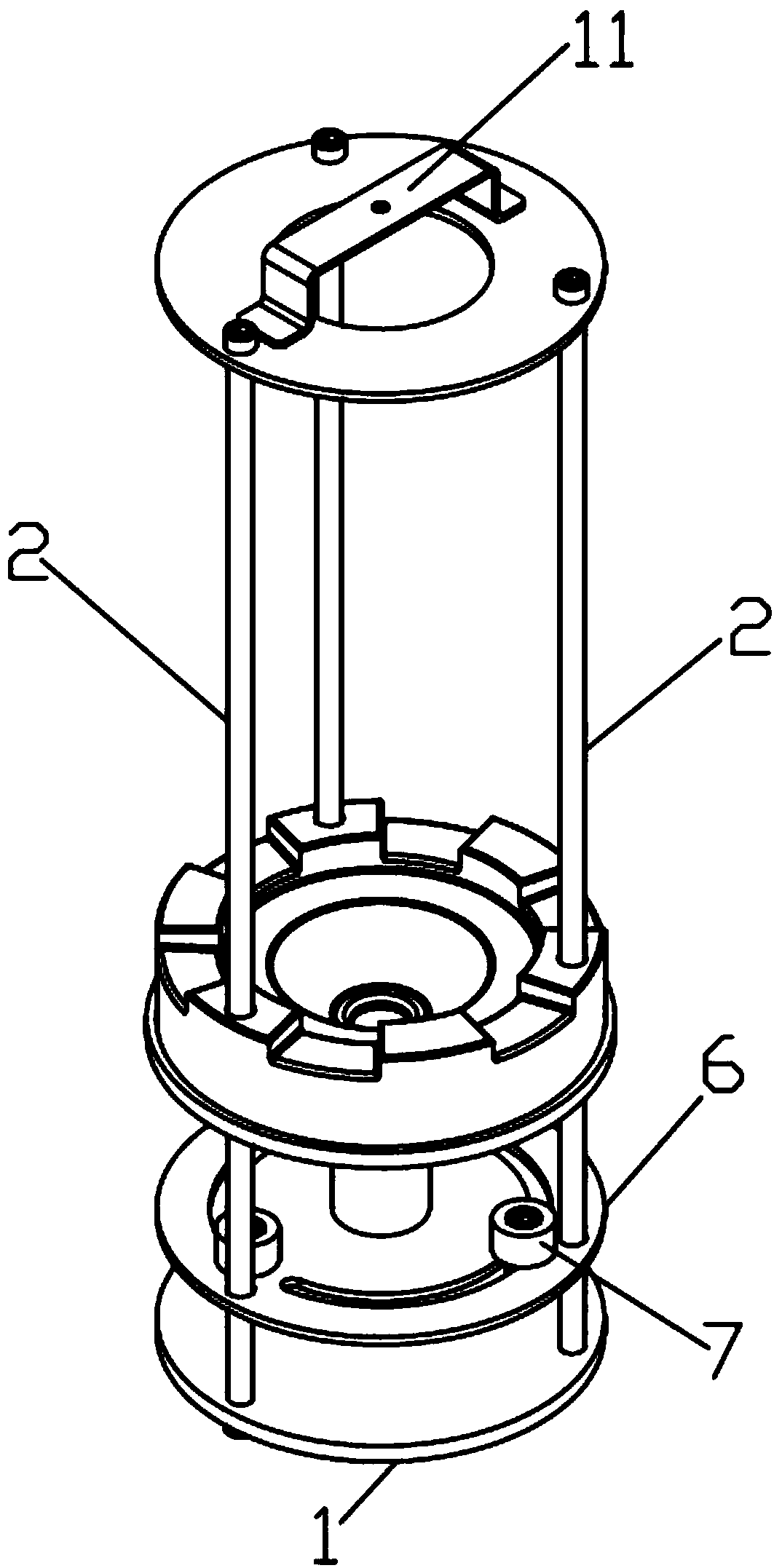
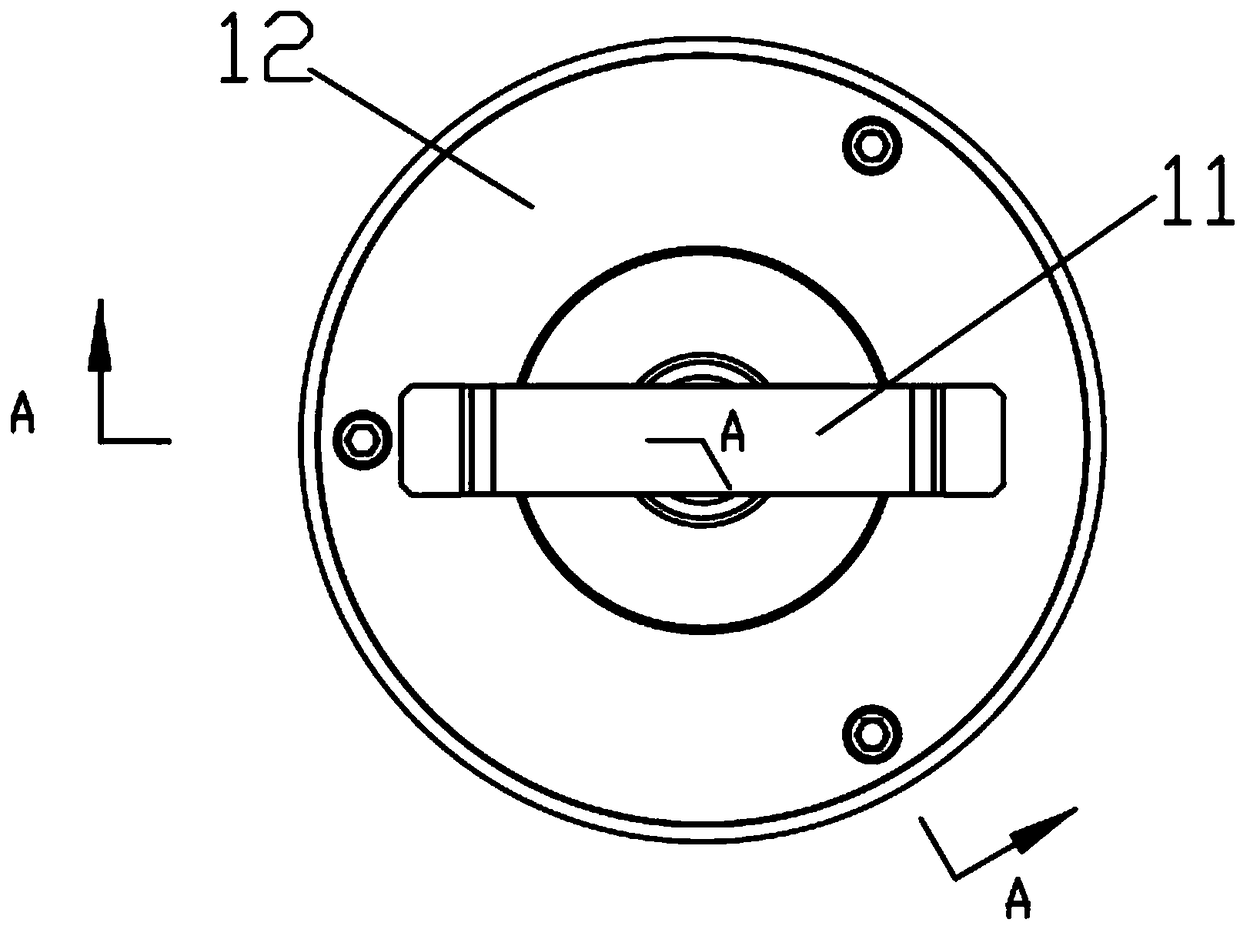
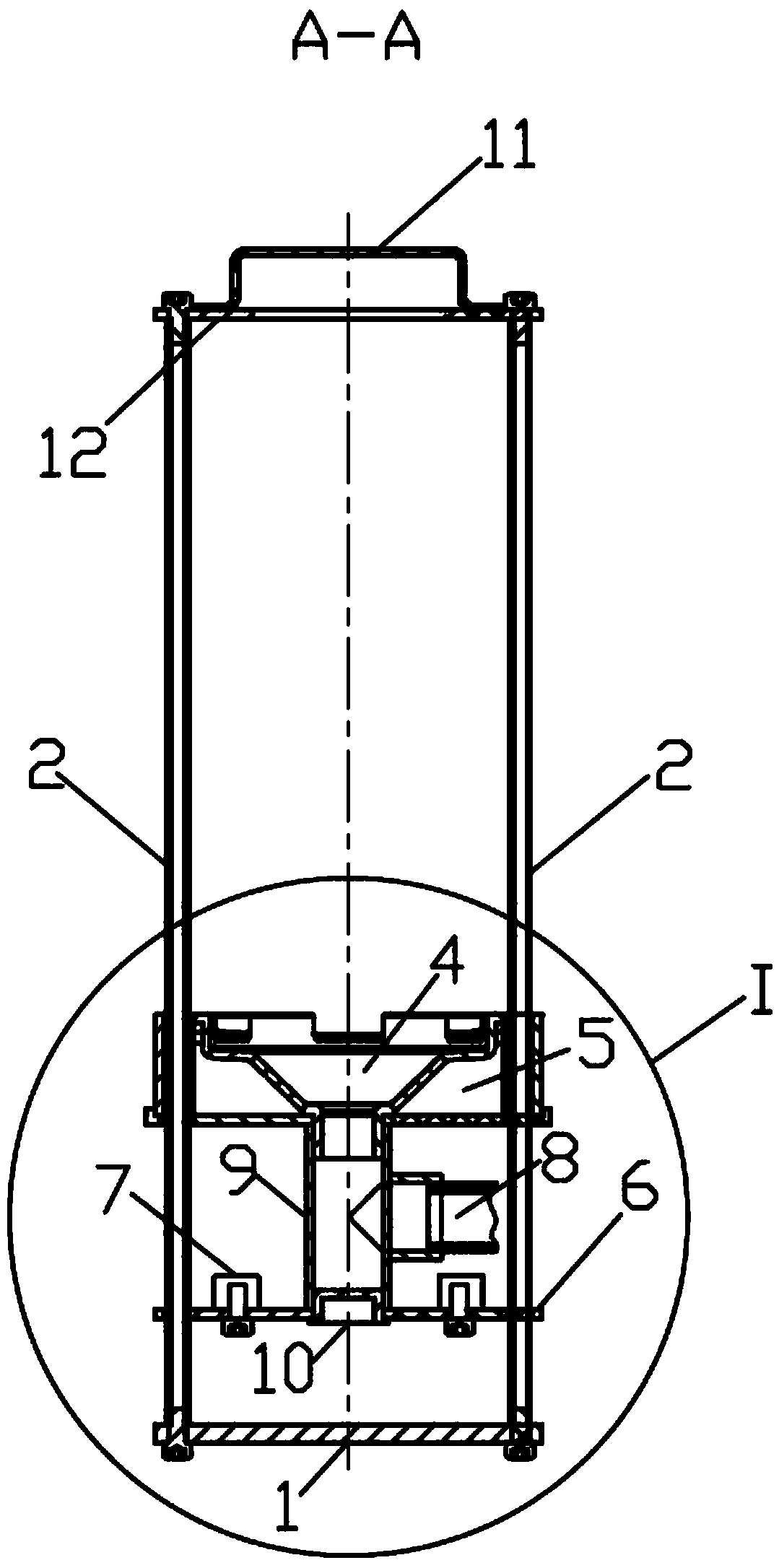
[0029] Depend on Figure 1-6 It can be seen from the illustrated embodiment that this embodiment includes a waste oil collector vertical guide support and a waste oil collector, and the waste oil collector vertical guide support includes a base 1 and a waste oil collector vertical guide set above the base 1 Guide rail 2; waste oil collector is provided with guide hole 3, waste oil collection chamber 4, buoyancy generation chamber 5, counterweight placement plate 6, counterweight 7 and oil discharge pipe which are slidingly connected with waste oil collector vertical guide rail 2 8. The upper and lower ends of the waste oil collection chamber 4 are open, including the oil separation port, the oil guide chamber 4-1 and the oil outlet 4-2. The oil separation port is located on the upper edge of the oil guide chamber 4-1. The notches 4-3...


PUM


Abstract

The invention discloses a cutting fluid waste oil clearing device, and belongs to the technical field of cutting fluid waste oil clearing. The cutting fluid waste oil clearing device comprises a wasteoil collector vertical guide support seat and a waste oil collector, wherein the waste oil collector vertical guide support seat comprises a base and a waste oil collector vertical guide rail arranged above the base; the waste oil collector is provided with a guide hole, a waste oil collecting cavity, a buoyancy generating cavity, a counterweight placing disc, a counterweight and an oil discharging pipe; the guide hole is glidingly matched and connected with the waste oil collector vertical guide rail; openings are formed in the upper end lower ends of the waste oil collecting cavity, and comprise an oil liquid separation opening and an oil guide cavity and oil outlet opening; the oil liquid separation opening is positioned at the upper edge of the oil guide cavity and consists of a plurality of annularly distributed notches; the bottom edge of each notch is a flat edge, and is positioned at the same horizontal height; the oil outlet is an opening formed in the lower end of the oil guide cavity and is connected with an oil discharging pipe; the buoyancy generating cavity is positioned at the outer side of the waste oil collecting cavity. The cutting fluid waste oil clearing devicehas the advantages that the waste oil clearing efficiency is high; the work is stable and reliable; the continuous unintermitted automatic work can be realized, and the like.

Description

technical field [0001] The invention relates to the technical field of cutting fluid waste oil removal. Background technique [0002] In the process of metal processing, high temperature and friction will be generated between the cutting tool and the workpiece due to the cutting force, so it is necessary to use cutting fluid (emulsion) to lubricate and cool. Cutting fluid is recycled during machining. If it is polluted by oil during use, it will affect the machining accuracy of the parts and the service life of the equipment. However, in actual production, due to leakage and other reasons, some lubricating oil and hydraulic oil will inevitably be brought into the cutting fluid of the machine tool, and long-term accumulation will form an oil film on the surface of the cutting fluid. In this way, when the parts are processed, anaerobic bacteria will grow in the cutting fluid under the action of high temperature generated by the cutting force, causing the cutting fluid to dete...

Claims


Application Information

Patent Timeline
Patent Type & Authority Applications(China)
IPC IPC(8): B23Q11/00B01D17/032
CPCB23Q11/10B01D17/0214
Inventor 杨俊学史昊天张敬爽王丹王成龙丰志良苏艳杰刘一飞程磊
Owner 逸乐(廊坊)环保科技有限公司
Why Eureka
Try Eureka