Grinding method for wafer locating ring, wafer locating ring and application thereof and chemical-mechanical polishing device of wafer locating ring
A grinding method and positioning ring technology, which is applied to grinding devices, grinding machine tools, and other chemical processes, can solve the problems of being less than or equal to 0.01mm and poor flatness of wafer positioning rings, and achieve good flatness and flatness. The effect of good controllability of degree and condition
- Summary
- Abstract
- Description
- Claims
- Application Information
AI Technical Summary
Problems solved by technology
Method used
Image

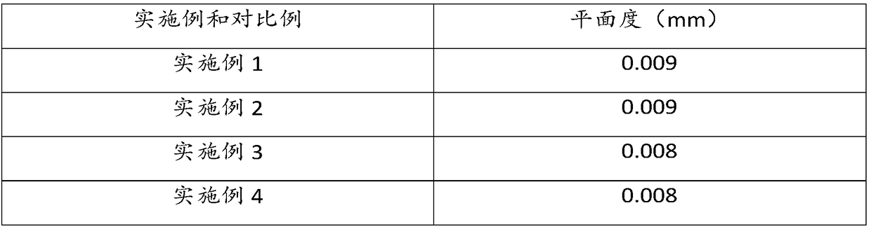
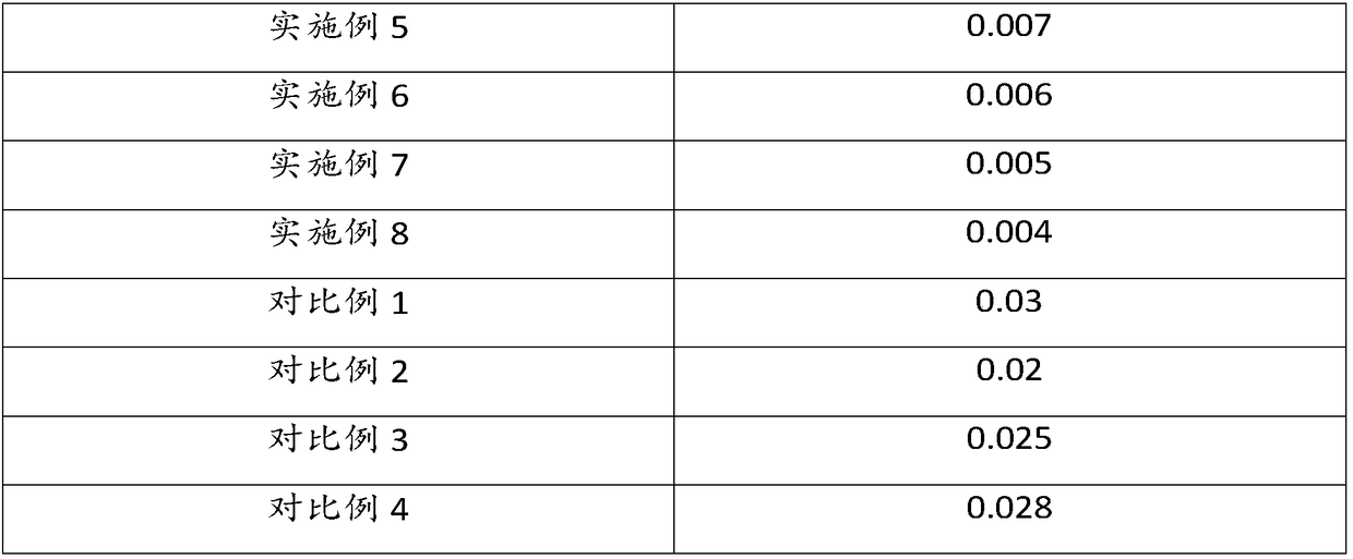
Examples
Embodiment 1
[0082] A grinding method of a wafer positioning ring, comprising the steps of:
[0083] Fix the wafer positioning ring on the polishing head, place the polishing pad on the grinding disc, add the abrasive liquid for polishing, and apply pressure to the polishing head at the same time;
[0084] Wherein, the grinding speed is 53 rpm, the grinding time is 37 min, the flow rate of the grinding liquid is 0.7 mL / s, and the pressure is 4.3 kg.
Embodiment 2
[0086] A grinding method of a wafer positioning ring, comprising the steps of:
[0087] Fix the wafer positioning ring on the polishing head, place the polishing pad on the grinding disc, add the abrasive liquid for polishing, and apply pressure to the polishing head at the same time;
[0088] Wherein, the grinding speed is 80 rpm, the grinding time is 35 min, the flow rate of the grinding liquid is 0.7 mL / s, and the pressure is 4.8 kg.
Embodiment 3
[0090] A grinding method of a wafer positioning ring, comprising the steps of:
[0091] Fix the wafer positioning ring on the polishing head, place the polishing pad on the grinding disc, add the abrasive liquid for polishing, and apply pressure to the polishing head at the same time;
[0092] Among them, the grinding speed is 50rpm, the grinding time is 35min, the flow rate of the grinding liquid is 0.7mL / s, and the pressure is 4.3kg;
[0093] Grinding fluid comprises the following components by weight percentage:
[0094] Benzotriazole 1%, Sodium Lauryl Sulfate 12%, Aluminum Oxide 12% and Water 75%;
[0095] Among them, the particle size of alumina is 30mm;
[0096] Grinding disc comprises the following components by weight percentage:
[0097] Resin 60%, Atomized Iron Powder 35% and Cocoyl Ethanolamine 5%;
[0098] Wherein, the particle size of the grinding disc is 300 mesh.
PUM
| Property | Measurement | Unit |
|---|---|---|
| particle diameter | aaaaa | aaaaa |
| particle diameter | aaaaa | aaaaa |
| particle size | aaaaa | aaaaa |
Abstract
Description
Claims
Application Information