Coring equipment and coring process

A kind of equipment and inner core technology, which is applied in the field of coring equipment and coring technology, can solve the problems of low processing efficiency, material waste, low efficiency, etc., and achieve the effect of preventing dust from flying, improving the working environment, and preventing splashing everywhere

Pending Publication Date: 2018-11-23
墨脱县墨脱石锅文化产业有限公司
View PDF0 Cites 4 Cited by
  • Summary
  • Abstract
  • Description
  • Claims
  • Application Information

AI Technical Summary

Problems solved by technology

[0002] In the processing industry, it is often encountered that an inner core needs to be taken out of the stone to form a cylindrical groove (the stone is not directly pierced), and the existing technology usually uses a chisel to slowly chisel the stone Go down, and then polish the side of the groove. This technology will cause waste of materials. The stone waste will be treated as garbage, and this kind of processing costs a lot of manpower and material resources, and the efficiency is low.
[0003] The same situation is often encountered in the jade and wood processing industries. Usually, the processing equipment is chisel or cutting tool, the processing efficiency is low, and fast coring cannot be achieved.

Method used


Image

  • Coring equipment and coring process
  • Coring equipment and coring process
  • Coring equipment and coring process

Examples


Embodiment 1

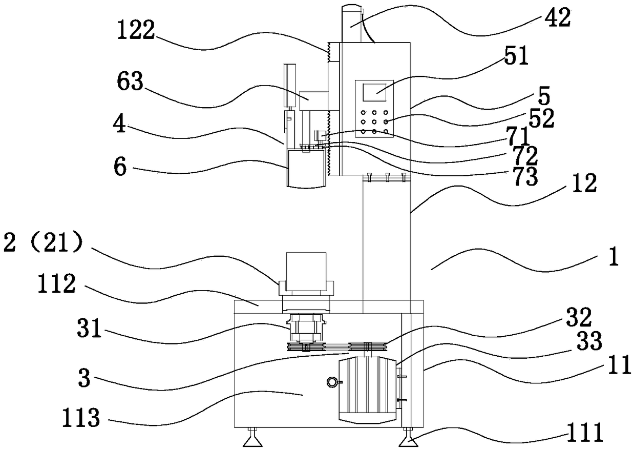
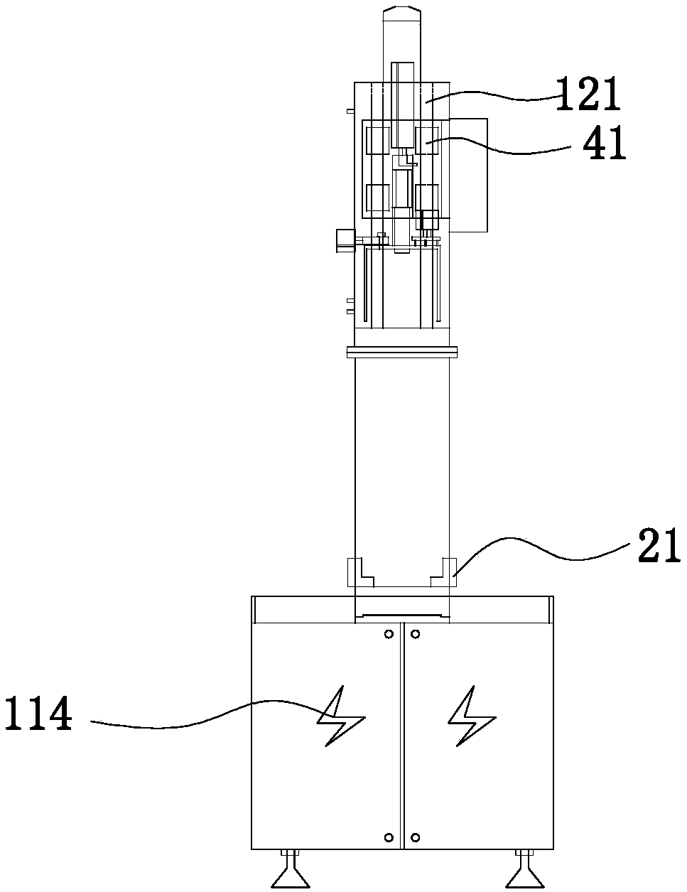
[0048] Refer to attached Figure 1-9 As shown, a coring device includes a main body 1, the main body 1 includes a base 11 and a support 12, the base 11 is connected and fixed to the support 12, the base 11 is a cuboid workbench, and the four corners of the base 11 are provided with The adjustment feet 111 are used for adjusting the overall height of the base 11 . The top surface of the base 11 is provided with a water blocking plate 112, and the water blocking plate 112 forms a concave cavity around the top surface to prevent water from flowing out from around the top surface of the base 11. Further, a water opening is provided in the concave cavity, and the water opening runs through the base 11 , so that water flows out from the top surface of the base 11 to the bottom surface of the base 11, and further, it can be introduced into the sewer pipe by connecting a water pipe.

[0049]The base 11 is provided with a clamping assembly 2 and a rotating assembly 3. The clamping ass...

Embodiment 2

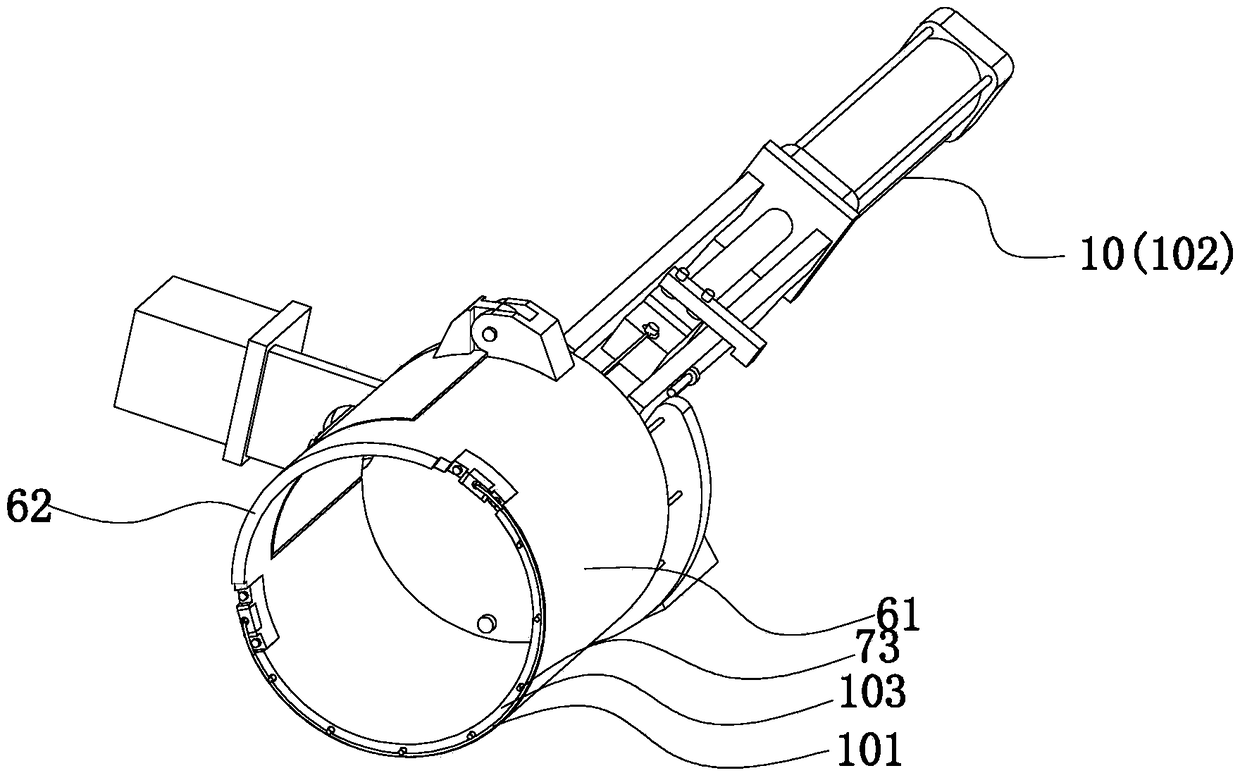
[0064] Refer to attached Figure 10 As shown, the difference between Embodiment 2 and Embodiment 1 is that the rotating assembly 3 is located on the coring assembly 4, that is, the clamping assembly 2 is fixed, and the rotating assembly 3 specifically drives the punching tool 61 Rotate, and its specific rotation is driven by the motor to drive the cutter pad 63 to rotate, driving the punching cutter 61 to rotate.

Embodiment 3

[0066] Refer to attached Figure 11 As shown, the difference between Embodiment 3 and Embodiment 1 is that it also includes a protective cover 81, the control mechanism is located on the protective cover 81, the protective cover 81 cooperates with the base 11 to form a sealed chamber, and the clamping assembly 2, Both the coring assembly 4 and the support 12 are located in the chamber. For the convenience of observation, the protective cover 81 adopts a transparent setting, and the protective cover 81 is provided with a window, which is convenient for placing and taking raw materials.

[0067] The setting of the closed chamber improves the working environment of the operator and prevents the dust from splashing everywhere. The operator only needs to open the protective cover 81 when picking up the material, and it is controlled by the control mechanism on the protective cover 81, that is, The process of coring can be realized.


PUM


Abstract

The invention discloses coring equipment and a coring process. The coring equipment comprises a body, the body comprises a base and a supporting seat, the base is fixedly connected with the supportingseat, and a clamping assembly is arranged on the base and used for clamping a raw material. A coring assembly and a control assembly are arranged on the supporting seat, the coring assembly slides upand down relative to the supporting seat, and the control assembly controls the clamping assembly and the coring assembly to operate. The coring assembly is provided with a perforation mechanism, a limiting mechanism and a cutting mechanism, the perforation mechanism comprises a perforation tool, and the cutting mechanism comprises a cutting line which is positioned at the bottom of the perforation tool and limited through the limiting mechanism. In an initial state, the limiting mechanism limits motion of the cutting mechanism, the perforation mechanism rotates relative to the clamping assembly to realize perforation, and the perforation mechanism stops operating when the perforation depth reaches a preset value. The control assembly controls the limiting mechanism to stop limiting, andthe cutting line rotates relative to the clamping assembly to realize bottom cutting of an inner core of the raw material. The coring equipment has advantages of simple structure, convenience in coring, inner wall smoothness and the like.

Description

technical field [0001] The invention relates to a device, in particular to a coring device and a coring process. Background technique [0002] In the processing industry, it is often encountered that an inner core needs to be taken out of the stone to form a cylindrical groove (the stone is not directly pierced), and the existing technology usually uses a chisel to slowly chisel the stone Go down, and then polish the side of the groove. This technique will cause waste of materials, and the stone waste will be treated as garbage, and this kind of processing consumes a lot of manpower and material resources, and the efficiency is low. [0003] The same situation is often encountered in jade and wood processing industries. The usual processing equipment is chisels or cutting tools, which has low processing efficiency and cannot achieve fast coring. Contents of the invention [0004] The technical problem mainly solved by the present invention is to provide a coring device an...

Claims


Application Information

Patent Timeline
Patent Type & Authority Applications(China)
IPC IPC(8): B28D1/00B28D7/02B28D7/00B28D7/04B27C9/00B27G3/00
CPCB28D1/003B27C9/00B27G3/00B28D7/00B28D7/005B28D7/02B28D7/04
Inventor 周日庶
Owner 墨脱县墨脱石锅文化产业有限公司
Why Eureka
Try Eureka