Micro-aerobic environment moving bed biological film reaction device and method for utilizing same to treat coal gas wastewater

A technology of moving bed biofilm and reaction device, which is applied in the field of water treatment device and coal gas wastewater treatment, can solve the problems of long hydraulic retention time, high treatment cost and poor effect, and achieve small sludge output and residual waste Less amount of sludge, good treatment effect

Active Publication Date: 2018-11-23
HARBIN INST OF TECH
View PDF5 Cites 2 Cited by
  • Summary
  • Abstract
  • Description
  • Claims
  • Application Information

AI Technical Summary

Problems solved by technology

[0004] The purpose of the present invention is to solve the problems of poor pollutant removal effect, long hydraulic retention time and high treatment cost of the existing equipment for treating coal gas wastewater, and provide a micro-oxygen environment moving bed biofilm Reaction device and method for treating waste water from coal gas production using the same

Method used


Image

  • Micro-aerobic environment moving bed biological film reaction device and method for utilizing same to treat coal gas wastewater
  • Micro-aerobic environment moving bed biological film reaction device and method for utilizing same to treat coal gas wastewater
  • Micro-aerobic environment moving bed biological film reaction device and method for utilizing same to treat coal gas wastewater

Examples


specific Embodiment approach 1

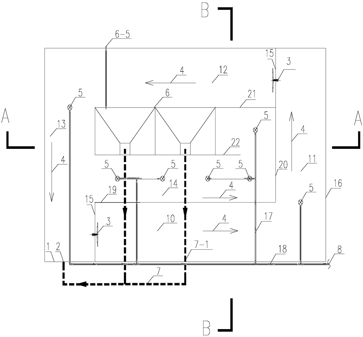
[0025] Specific implementation mode one: combine figure 1 Describe this embodiment mode, a kind of micro-oxygen environment moving bed biofilm reaction device of this embodiment comprises tank body 16, two underwater thrusters 3, a plurality of aeration heads 5, sludge return pipe main pipe 7, air pump 8, Settling tank 6, pusher fixing rod 15, first partition wall 19, second partition wall 20, third partition wall 21 and fourth partition wall 22;

[0026] Described pond body 16 is provided with sedimentation tank 6 and four partition walls, and four partition walls are arranged on the outside of sedimentation tank 6; Described four partition walls are respectively the first partition wall 19, the second partition wall 20. The third partition wall 21 and the fourth partition wall 22; the pool body 16 is divided into five corridors by the sedimentation tank 6 and four partition walls; the five corridors are respectively the first corridor 10 and the second corridor 11. The thir...

specific Embodiment approach 2

[0044] Specific embodiment 2: The difference between this embodiment and specific embodiment 1 is: the push flow direction of the underwater pusher 3 is along the outlet end of the first corridor 10, the inlet end of the second corridor 11, The exit end of the second corridor 11, the entrance end of the third corridor 12, the exit end of the third corridor 12 and the entrance end of the fourth corridor 13 direction push flow, the first corridor 10, the second corridor 11 , The third corridor 12 and the fourth corridor 13 are rotary corridors in the form of oxidation ditch, which can rotate and circulate. Other steps are the same as in the first embodiment.

specific Embodiment approach 3

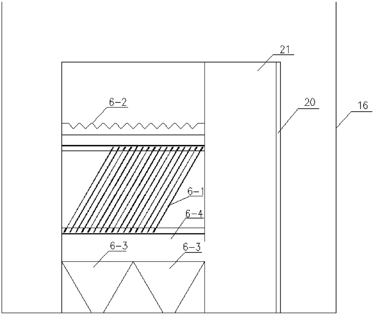
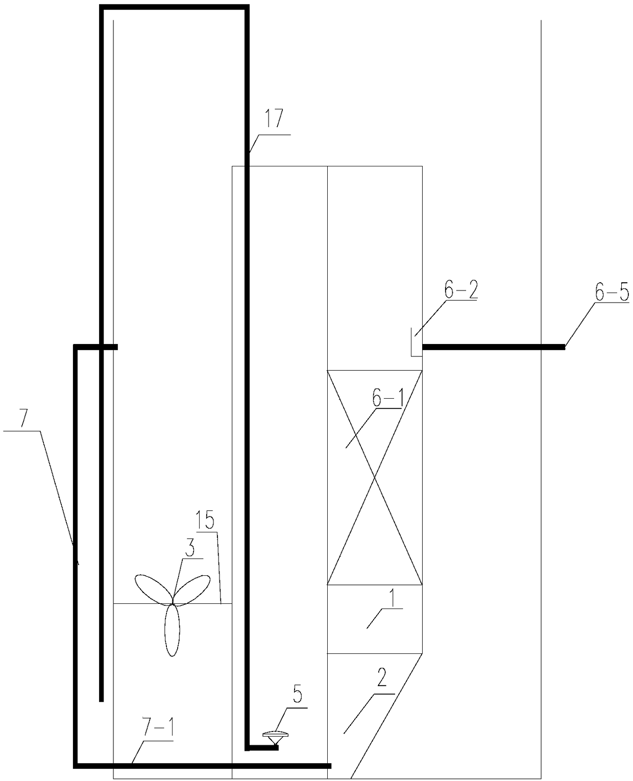
[0045] Specific implementation mode three: combination Figure 1 ~ Figure 3 Describe this embodiment, the difference between this embodiment and specific embodiment 1 or 2 is: the sedimentation tank 6 is a slant plate sedimentation tank, the middle part of the slant plate sedimentation tank is a slant plate 6-1, and the slant plate 6- The upper part of 1 is the outlet weir 6-2, the lower part of the inclined plate 6-1 is provided with the sedimentation tank inlet area 6-4, and the lower part of the sedimentation tank inlet area 6-4 is provided with two mud storage tanks 6-3, and the sedimentation tank One end of the outlet pipe 6-5 of the pool communicates with the outlet weir 6-2, and the other end passes through the pool body 16. Other steps are the same as those in Embodiment 1 or 2.

[0046] Specific implementation mode four: combination Figure 1 ~ Figure 3 Describe this embodiment. The difference between this embodiment and one of the specific embodiments 1 to 3 is: th...


PUM

PropertyMeasurementUnit
particle diameteraaaaaaaaaa

Abstract

The invention provides a micro-aerobic environment moving bed biological film reaction device and a method for utilizing the same to treat coal gas wastewater, and relates to a water treatment deviceand a method for utilizing the device to treat the coal gas wastewater. The micro-aerobic environment moving bed biological film reaction device solves the problems that the effect of an existing coalgas wastewater treatment device on removing the pollutants in the coal gas wastewater is poor, the hydraulic retention time is long, and the treatment fee is high. The micro-aerobic environment moving bed biological film reaction device comprises a pond body, two underground water impellers, two aeration heads, a sludge return pipe header pipe, an air pump, a settling pond, a water impeller fixing rod and a partition wall. The method comprises the steps that 1, the coal gas wastewater enters the pond body from a water inlet pipe and a water inlet through the gravity flow hydraulic dropping mode, and the underground water impellers are opened; 2, the air pump, a valve on an aeration branch pipe, a valve on a sludge return pipe branch pipe and an electromagnetic valve are opened; 3, a biological film filler is added; and 4, hydraulic retention is conducted. The method is suitable for treating the coal gas wastewater.

Description

technical field [0001] The invention relates to a water treatment device and a method for treating coal gas waste water by using the device. Background technique [0002] my country's petrochemical resource characteristics of "rich in coal, poor in oil, and lack of gas" determine that my country must develop a modern coal chemical industry. In response to the current situation of insufficient oil and natural gas resources and rapid growth in demand, coal-to-gas will quickly become one of the leading industries in the modern coal chemical industry to make up for the current situation of insufficient clean fuels. The country's advocacy of high-efficiency and clean energy, the need to develop alternative energy sources for oil, the need to make full use of inferior coal resources, and the requirements to reduce environmental pollution have brought a broad market to the development of the modern coal-to-gas industry. Therefore, in the coming decades of transition to clean new e...

Claims


Application Information

Patent Timeline
Patent Type & Authority Applications(China)
IPC IPC(8): C02F3/02C02F3/34C02F101/16C02F103/34C02F101/34
CPCC02F3/02C02F3/34C02F2101/16C02F2101/345C02F2103/34Y02W10/10
Inventor 韩洪军左世昌徐春艳
Owner HARBIN INST OF TECH
Why Eureka
Try Eureka