
Micro-interval steel mesh template electric polishing technology

A micro-pitch, electro-polishing technology, applied in the direction of metal material coating process, can solve the problems of product quality decline, processing precision reduction, solder paste damage, etc., to achieve the effect of improving processing precision and reducing processing difficulty

Inactive Publication Date: 2018-11-23
光宏光电技术(深圳)有限公司
View PDF3 Cites 2 Cited by
  • Summary
  • Abstract
  • Description
  • Claims
  • Application Information

AI Technical Summary

Problems solved by technology

[0003] After the stencil is laser engraved, there are burrs on the hole wall. After the solder paste is printed, the burrs will damage the printed solder paste
Causes the reduction of product processing accuracy and product quality. In order to solve this problem, further improvement on the basis of existing technology is required.

Method used


Image

  • Micro-interval steel mesh template electric polishing technology

Examples


Embodiment 1

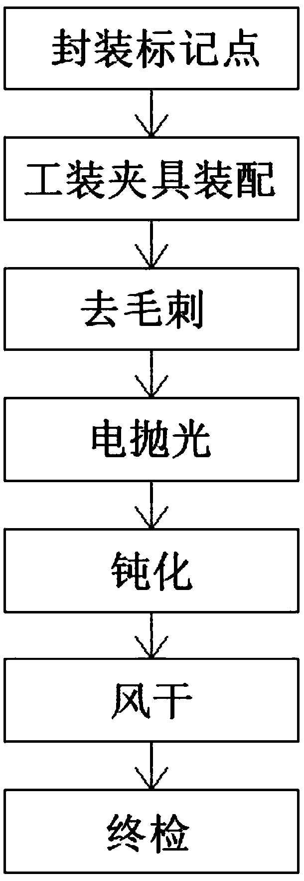
[0036] The micro-pitch stencil electropolishing process includes the following steps:

[0037] Step 1: Encapsulate marker points:

[0038] 1.1. Place the steel sheet to be polished on the inspection table for preliminary inspection to confirm whether there are creases on the surface of the steel sheet and whether the pad is deformed, and give feedback in time.

[0039] 1.2. Use alcohol to wipe the area of ​​the marking points pre-set on the steel sheet to ensure that the surface of the marking points is clean, then use the round adhesive tape to seal the marking points tightly, and ensure that the marking points are placed in the center of the round adhesive tape.

[0040] 1.3. Put the steel sheet in the grinding machine and grind it on both sides to improve the processing accuracy of the steel sheet. After grinding, use a brush to clean the opening area on the printing surface in the vertical and horizontal directions, so as to facilitate the hole diameter comparison and clea...

Embodiment 2

[0058] The micro-pitch stencil electropolishing process includes the following steps:


PUM


Abstract

The invention discloses a micro-interval steel mesh template electric polishing technology. The micro-interval steel mesh template electric polishing technology comprises the steps that firstly, marking point packaging is conducted; secondly, tool clamp assembling is conducted; thirdly, deburring is conducted; fourthly, polishing is conducted; fifthly, passivation is conducted; and seventhly, final checking is conducted. The micro-interval steel mesh template electric polishing technology has the beneficial effects that the micro-interval steel mesh template electric polishing technology is provided, the hole wall burr point discharge and rapid dissolving principle is utilized, steel mesh template via hole wall burrs are sufficiently removed, sawteeth are flattened through cutting, and theeffect of smooth hole walls is achieved; and meanwhile, the hole size and the template thickness are not changed, printed solder paste is round and smooth, and the machining precision is improved while the machining difficulty is lowered.

Description

technical field [0001] The invention relates to the technical field of stencil template processing technology, in particular to the electropolishing process of a micro-pitch steel mesh template. Background technique [0002] Steel mesh, also known as SMT template, is a special mold for SMT. Its main function is to aid in the deposition of solder paste; the purpose is to transfer the exact amount of solder paste to the exact location on the empty PCB. Steel mesh was originally made of wire mesh, so it was called stencil at that time. At first, it was nylon (polyester) mesh, and later due to durability, barbed wire mesh, copper wire mesh appeared, and finally stainless steel mesh. But no matter what material the screen is made of, it has the disadvantages of poor molding and low precision. With the development of SMT, the requirements for stencils have increased, and stencils have been produced. Affected by the cost of materials and the difficulty of production, the origin...

Claims


Application Information

Patent Timeline
IPC IPC(8): C25F3/24C25F3/06C23C22/05
CPCC23C22/05C25F3/06C25F3/24
Inventor 陈孟财
Owner 光宏光电技术(深圳)有限公司
Learn More