
Single-relay wireless energy transmission system parameter design method

A technology of wireless power transmission and system parameters, applied in the direction of circuit devices, electrical components, etc., can solve the problems of system control complexity increase, lack, increase system order, etc., to guide system design, improve robustness, and enhance freedom degree of effect

Active Publication Date: 2018-11-23
CHONGQING UNIV
View PDF8 Cites 9 Cited by
  • Summary
  • Abstract
  • Description
  • Claims
  • Application Information

AI Technical Summary

Problems solved by technology

At present, there is a lack of a complete set of theoretical design criteria, which can quickly and accurately obtain the critical coupling value of each parameter of the MC-WPT system
At the same time, changing the intrinsic parameters of the system to make the system exit the over-coupling region may reduce the maximum transmission efficiency of the system
Moreover, increasing the impedance matching network will increase the order of the system accordingly, so the complexity of system control will also increase accordingly
Adjusting the coupling strength of the system is generally achieved by mechanically adjusting the relative position of the resonator, so it is not suitable for systems where the position of the resonator is relatively fixed or needs to be constantly moved

Method used


Image

  • Single-relay wireless energy transmission system parameter design method
  • Single-relay wireless energy transmission system parameter design method
  • Single-relay wireless energy transmission system parameter design method

Examples


Embodiment Construction

[0033] Embodiments of the technical solutions of the present invention will be described in detail below in conjunction with the accompanying drawings. The following examples are only used to illustrate the technical solutions of the present invention more clearly, and therefore are only examples, rather than limiting the protection scope of the present invention.

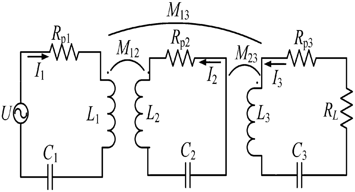
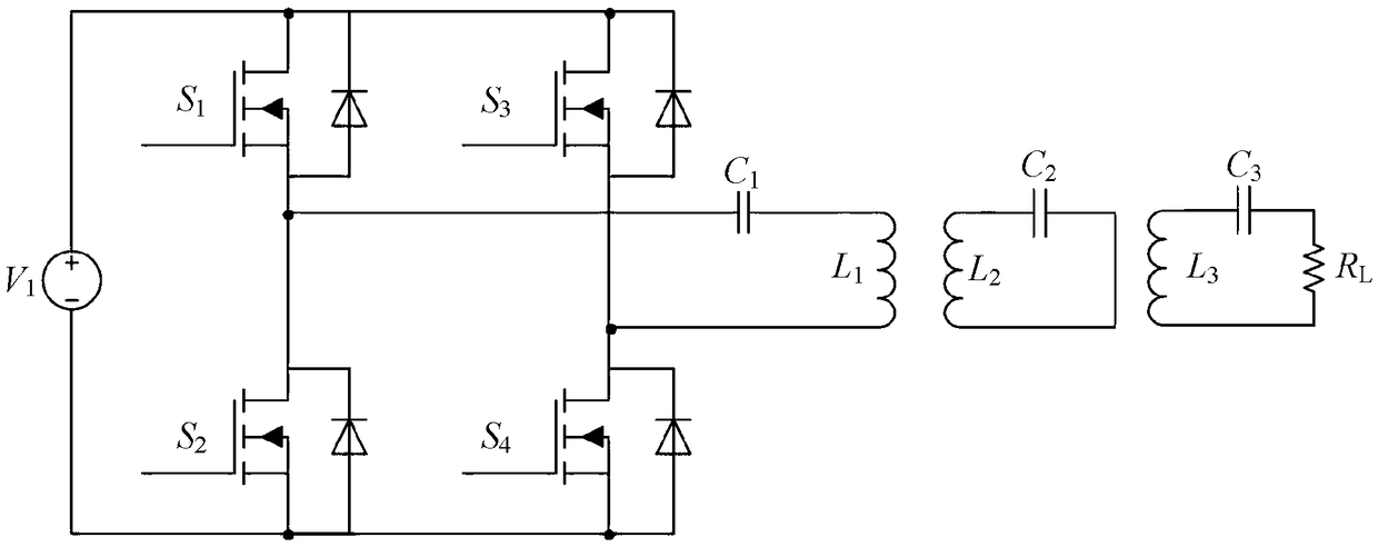
[0034] This embodiment adopts as figure 1 The single-relay wireless power transfer system shown includes a DC power supply V 1 , switch tube S 1 ~S 4 Composed of high-frequency inverter, transmitting coil compensation capacitor C 1 , Transmitting coil L 1 , relay coil L 2 , Relay coil compensation capacitance C 2 , receiving coil L 3 , receiving coil compensation capacitance C 3 and the equivalent load R L , the circuit components are connected as figure 2 shown.

[0035] To set its parameters, follow the steps below:

[0036] S1: Determine the circuit topology of the single-relay wireless power transf...


PUM


Abstract

The invention discloses a single-relay wireless energy transmission system parameter design method. The single-relay wireless energy transmission system parameter design method is characterized by comprising the following steps: S1: a circuit topological structure of the single-relay wireless energy transmission system is determined; S2, self-inductance and coil internal resistance values of the three coils are determined; S3, the working frequency, the mutual inductance parameter and the load resistance value are determined; S4, the capacitance value of an emission coil compensation capacitoris determined; S5, a quality factor and a coupling coefficient are determined; S6, a detuning factor of each loop is defined; S7, a discriminant D is calculated; S8, the optimal detuning factor is determined according to the discriminant; S9, according to the optimal detuning factor, the capacitance values of a relay coil compensator capacitor and a receiving coil compensation capacitor are determined; and S10, the feasibility of all parameters of the system is verified. The single-relay wireless energy transmission system parameter design method provided by the invention has the effects thatthe method is suitable for systems of any frequency, the orientation robustness of the system is greatly improved, and the system design can be effectively guided.

Description

technical field [0001] The invention relates to the field of wireless power transmission, in particular to a method for designing parameters of a single-relay wireless power transmission system. Background technique [0002] Magnetically coupled wireless power transfer (MC-WPT) technology realizes the transmission of electric energy from the power supply side to the electrical equipment end without electrical connection, completely gets rid of the shackles of wires, has broad market prospects and scientific research value, and has been widely used in households Electrical appliances, biomedicine, electric vehicles and other fields. According to the classification of system structure, MC-WPT system can be divided into two-coil structure, three-coil structure, four-coil structure and multi-coil (domino) structure. The three-coil structure, also known as a single-relay system, has become a research hotspot in this field because it can take into account both transmission effici...

Claims


Application Information

Patent Timeline
Patent Type & Authority Applications(China)
IPC IPC(8): H02J50/10H02J50/12H02J50/50
CPCH02J50/10H02J50/12H02J50/50
Inventor 孙跃叶兆虹苏玉刚唐春森王智慧廖志娟
Owner CHONGQING UNIV
Learn More