Industrial oily wastewater treatment system

A wastewater treatment system and industrial technology, applied in multi-stage water treatment, water/sewage treatment, flotation water/sewage treatment, etc., can solve problems such as unsatisfactory treatment effects, reduce floor space and improve treatment efficiency Effect

Inactive Publication Date: 2018-11-27
浙江海之蓝环保科技有限公司
View PDF6 Cites 2 Cited by
  • Summary
  • Abstract
  • Description
  • Claims
  • Application Information

AI Technical Summary

Problems solved by technology

However, the treatment effect of any one of the above three methods is not satisfactory, so an industrial oily wastewater treatment system is needed to reasonably treat the process oily wastewater to achieve the expected discharge index

Method used


Image

  • Industrial oily wastewater treatment system
  • Industrial oily wastewater treatment system
  • Industrial oily wastewater treatment system

Examples


Embodiment 1

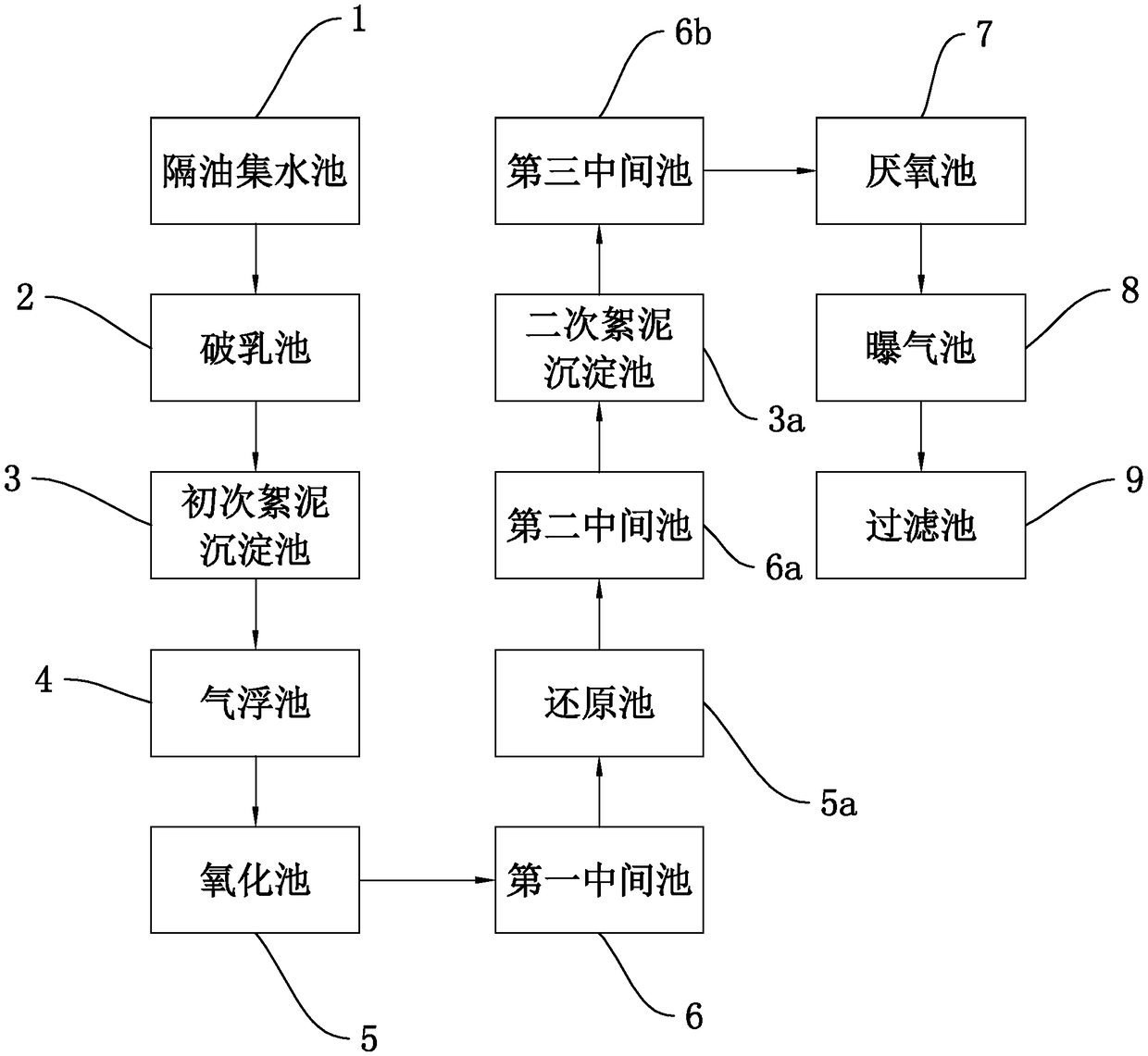
[0052] as attached figure 1 As shown, an industrial oily wastewater treatment system includes sequentially connected oil separation pool 1, demulsification tank 2, primary floc sedimentation tank 3, air flotation tank 4, oxidation tank 5, reduction tank 5a, secondary floc sedimentation pool 3a, anaerobic pool 7, aeration pool 8 and filter pool 9. A first intermediate pond 6 is arranged between the oxidation pond 5 and the reduction pond 5a, and a second intermediate pond 6a is arranged between the reduction pond 5a and the secondary floc sedimentation pond 3a; the secondary floc sedimentation pond 3a and the anaerobic pond 7 There is a third intermediate pool 6b between them.

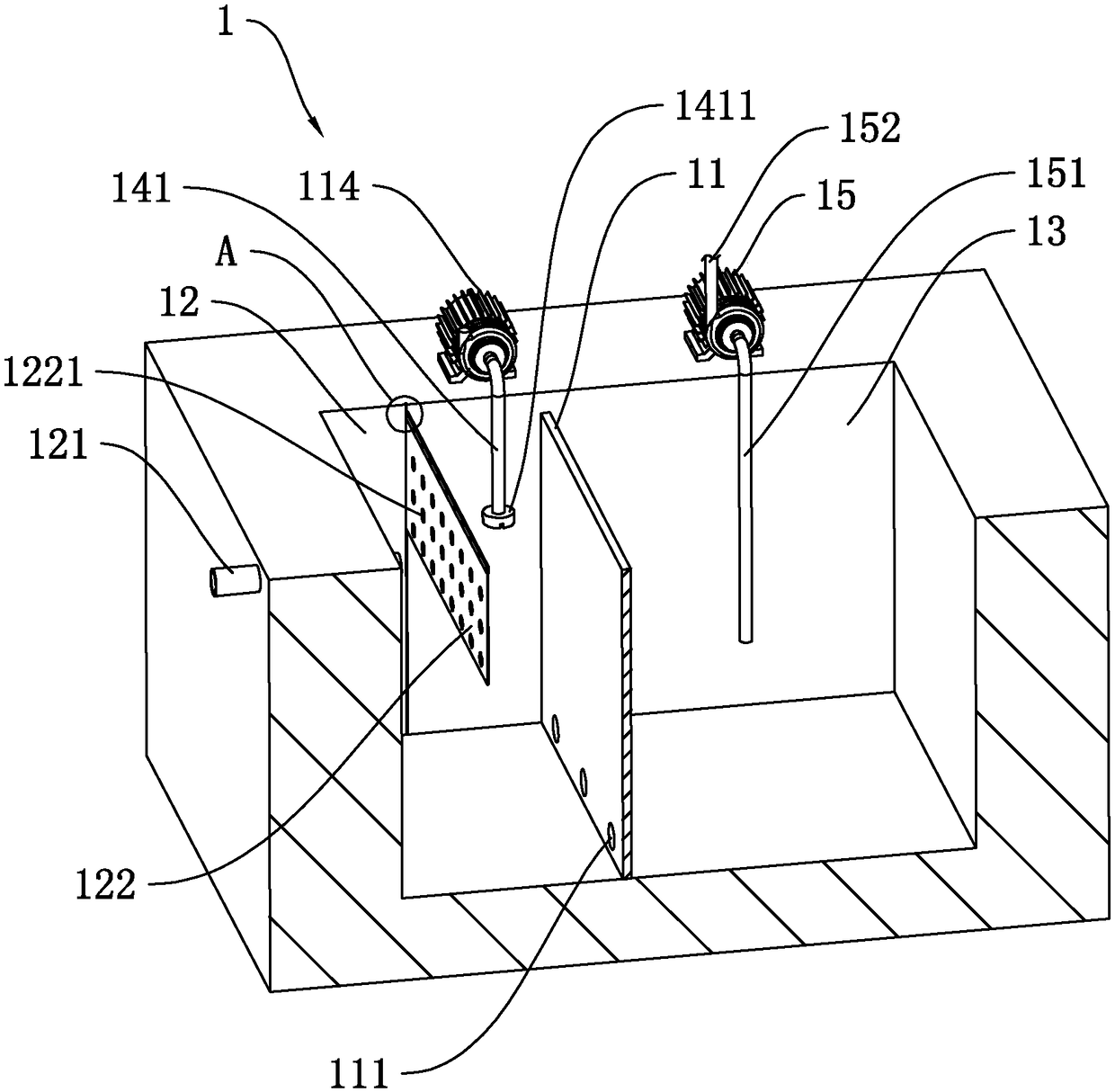
[0053] as attached figure 2 As shown, the shape of the oil separation sump 1 can be determined according to the actual situation, where it is cuboid and open at the top. An oil separator 11 is arranged in the oil separation pool 1 , and both sides and the bottom of the oil barrier 11 are sealed and ...

Embodiment 2

[0089] as attached Figure 18 Shown, a kind of industrial oily wastewater treatment system, it is based on the basis of embodiment 1, and its difference lies in the difference of oil separation sump 1. In the second embodiment, the oil separation pool 1 includes a liquid inlet pool 1a, an oil separation pool 1b, and a water separation pool 1c, which are arranged adjacently and communicate with each other at the upper end. The liquid inlet pool 1a and the oil separation pool 1b are separated by a first partition 1d, and the height of the first partition 1d is h1. The oil separation pool 1b and the water separation pool 1c are separated by a second partition 1e, and the height of the second partition 1e is h2.

[0090] The side wall of the liquid inlet pool 1a is connected with a liquid inlet pipe 121 communicating with oily waste water, and the height of the liquid inlet pipe 121 is lower than that of the first partition 1d. A buffer net 1a1 parallel to the first partition 1d...


PUM


Abstract

The invention relates to industrial wastewater treatment, and discloses an industrial oily wastewater treatment system. According to the technical scheme, the industrial oily wastewater treatment system comprises an oil separation and water collecting pond, a demulsification pond, a primary flocculated mud sedimentation pond, a flotation pond, an oxidation pond, a reduction pond, a secondary flocculated mud sedimentation pond, an anaerobic pond and an aeration pond which are successively connected, a first middle pond is arranged between the oxidation pond and the reduction pond, a second middle pond is arranged between the reduction pond and the secondary flocculated mud sedimentation pond, and a third middle pond is arranged between the secondary flocculated mud sedimentation pond and the anaerobic pond; oil and water are separated preliminarily by the oil separation and water collecting pond; the demulsification pond breaks the emulsion state of the separated wastewater; flocculatesof oil is settled in the primary flocculated mud sedimentation pond; and by chemical reaction in the oxidation pond and the reduction pond, macromolecular organic matters in the wastewater are decomposed; activated sludge is placed in the anaerobic pond and the aeration pond, and low molecular weight organic matters are biochemically degraded; and the industrial oily wastewater is treated by organically combining a physical treatment method, a chemical treatment method and a biological treatment method to achieve an expected emission standard, and thus, the industrial oily wastewater treatment system is effectively and practical.

Description

technical field [0001] The invention relates to industrial wastewater treatment, in particular to an industrial oily wastewater treatment system. Background technique [0002] Industrial processing and production often produce some oily wastewater. The oil components in these industrial oily wastewater come from some cutting fluids, cooling oils and waste liquids after washing. The oily wastewater has a high oil content and its component content tends to be stable. It cannot be discharged directly, and it needs to be treated and discharged after reaching the standard. [0003] Existing oily wastewater treatment methods generally include physical, chemical or biological methods. Most of the physical methods are methods such as static stratification and precipitation. The chemical method is to remove the oil components by adding chemicals to the oily wastewater. The biological method is to decompose the oil components through microbial degradation. However, the single use of...

Claims


Application Information

Patent Timeline
IPC IPC(8): C02F9/14C02F1/40C02F1/24
CPCC02F1/001C02F1/24C02F1/40C02F1/5236C02F1/56C02F1/70C02F1/72C02F3/30C02F9/00C02F2001/007C02F2301/08
Inventor 薛力军
Owner 浙江海之蓝环保科技有限公司
Why Eureka
Try Eureka