Pulse laser radar receiving circuit and system with ultra-wide single-shot measurement range

A pulsed laser and measuring range technology, applied in the field of distance measurement, can solve the problems of large measurement error, rising cost, and inability to achieve single-shot measurement

Active Publication Date: 2018-11-27
SUN YAT SEN UNIV
View PDF8 Cites 7 Cited by
  • Summary
  • Abstract
  • Description
  • Claims
  • Application Information

AI Technical Summary

Problems solved by technology

[0004] 1) The frontier time identification method cannot eliminate the walking error of the pulse echo signal, so the measurement error is often large;
[0005] 2) Although the constant ratio identification method can eliminate the walking error, it needs to cooperate with an accurate delay device. A relatively simple delay device will lead to an increase in error, and an accurate delay device will lead to an increase in cost;
[0006] 3) Both receiving circuits need to use variable gain amplifiers to provide dynamic range, and the receiving circuit implemented by using variable gain amplifiers not only has a very limited dynamic range, but also needs to repeatedly send multiple pulse signals to make the variable gain amplifiers Adjust the gain, the received pulse signal is useful after the gain adjustment is completed, so these two schemes will waste a lot of pulse signals, and cannot achieve the effect of single-shot measurement, that is, it is impossible to achieve any pulse signal is useful

Method used


Image

  • Pulse laser radar receiving circuit and system with ultra-wide single-shot measurement range
  • Pulse laser radar receiving circuit and system with ultra-wide single-shot measurement range
  • Pulse laser radar receiving circuit and system with ultra-wide single-shot measurement range

Examples


Embodiment Construction

[0030] The present invention will be further described in detail below in conjunction with the drawings and preferred specific embodiments.

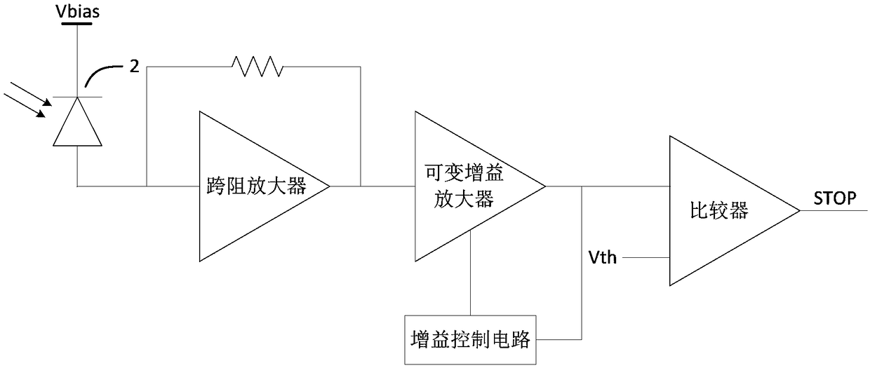
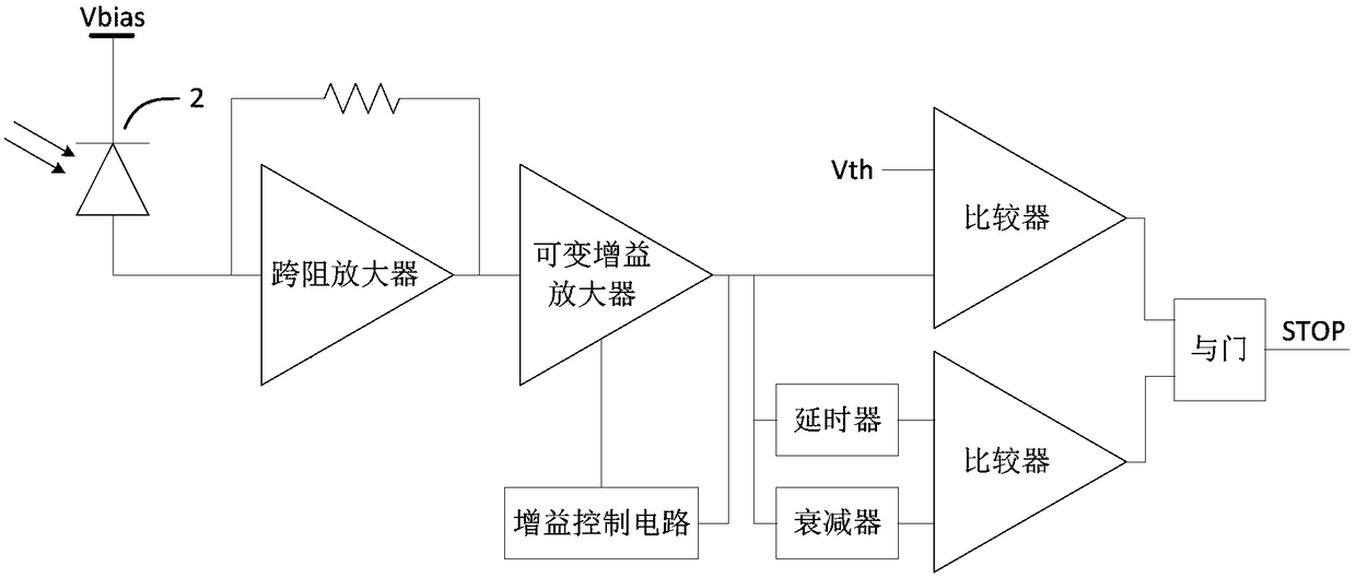
[0031] Such as Figure 4 As shown, a pulse laser radar receiving circuit with an ultra-wide single shot measurement range includes a dual bias resistor differential coupling circuit, a first processing link, a second processing link and a data selector.

[0032] For the dual bias resistor differential coupling circuit, it is used to input the current pulse signal converted by the photodiode PD into the first processing link and the second processing link in a differential manner;

[0033] For the first processing link, it includes a transimpedance amplifier circuit with current sourcing and sinking functions and a first moment discrimination circuit. The first output terminal of the dual bias resistor differential coupling circuit sequentially passes through the current sourcing and sinking function. The transimpedance amplifier circuit and th...


PUM


Abstract

The invention discloses a pulse laser radar receiving circuit with an ultra-wide single-shot measurement range, comprising a double bias resistor difference coupling circuit, a first processing link,a second processing link and a data selector; the first processing link comprises a transimpedance amplifying circuit with a current sourcing and sinking function and a first time discrimination circuit, wherein a first output end of the double bias resistor difference coupling circuit is connected to a first signal input end of the data selector by the transimpedance amplifying circuit with the current sourcing and sinking function and the first time discrimination circuit in turn; the second processing link comprises a sampling resistor and a second time discrimination circuit, wherein a second output end of the double bias resistor difference coupling circuit is connected to a second signal input end of the data selector by the sampling resistor and the second time discrimination circuit in turn. The receiving circuit provided by the invention has an ultra-wide dynamic range and has the advantage of low cost on the premise of achieving high measurement accuracy. The receiving circuit provided by the invention can be widely used in the field of distance measurement.

Description

Technical field [0001] The invention relates to the technical field of distance measurement, in particular to a pulse laser radar receiving circuit and system with an ultra-wide single shot measurement range. Background technique [0002] At present, the commonly used pulsed lidar system usually includes four parts: a controller, a transmitting drive circuit, a receiving circuit, and a high-precision time measurement module (such as figure 1 Shown), and use TOF (Time of Flight, time of flight) principle for distance measurement, the specific working principle is: when starting the distance measurement, the controller sends a "START" signal to the transmission drive circuit to drive the laser diode 1 to emit a narrow pulse laser At the same time, the "START" signal also triggers the high-precision time measurement module to start timing; when the pulsed laser is diffusely reflected by the target, the echo signal passes through the photodiode 2 to generate a current pulse signal, an...

Claims


Application Information

Patent Timeline
Patent Type & Authority Applications(China)
IPC IPC(8): G01S7/486
CPCG01S7/4861
Inventor 郭建平李开友
Owner SUN YAT SEN UNIV
Why Eureka
Try Eureka