
Suspension angle assembly of electric vehicle driven by hub motor

A hub motor and electric vehicle technology, applied in the direction of suspension, elastic suspension, cantilever installed on the pivot, etc., can solve the problem of affecting driving comfort and handling stability, affecting vehicle passability, large changes in steering operation, etc. Problems, to achieve the effect of reducing the negative effect of the unsprung on the vehicle, good steering flexibility and positive steering, and improving driving comfort

Pending Publication Date: 2018-11-30
JILIN UNIV
View PDF0 Cites 6 Cited by
  • Summary
  • Abstract
  • Description
  • Claims
  • Application Information

AI Technical Summary

Problems solved by technology

If the size of the small triangular lower swing arm is changed in order to keep the wheelbase constant, the kingpin offset will increase, the kingpin camber angle will decrease and the centering moment will increase, and the changes in the main parameters of the wheel will lead to changes in the steering operation. If it is too large, it will affect the original steering performance of the vehicle
If the triangular lower swing arm is not changed, the wheels will protrude outside the vehicle body, which will increase the vehicle width and affect the passability of the vehicle, and the installed in-wheel motor will increase the unsprung mass of the vehicle, which will affect the driving comfort and handling stability sex

Method used


Image

  • Suspension angle assembly of electric vehicle driven by hub motor
  • Suspension angle assembly of electric vehicle driven by hub motor
  • Suspension angle assembly of electric vehicle driven by hub motor

Examples


Embodiment Construction

[0020] The present invention will be described in detail below in conjunction with the accompanying drawings.

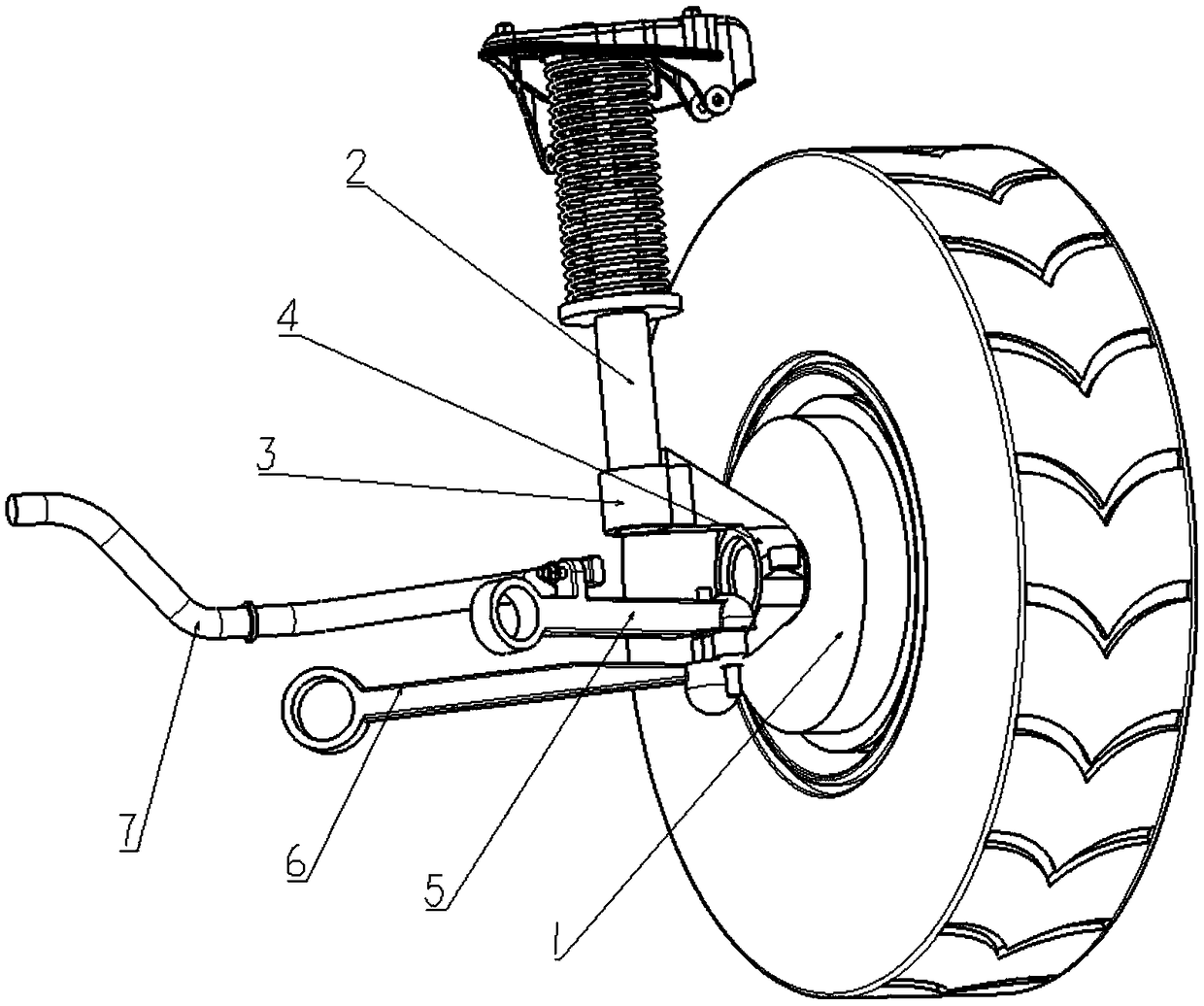
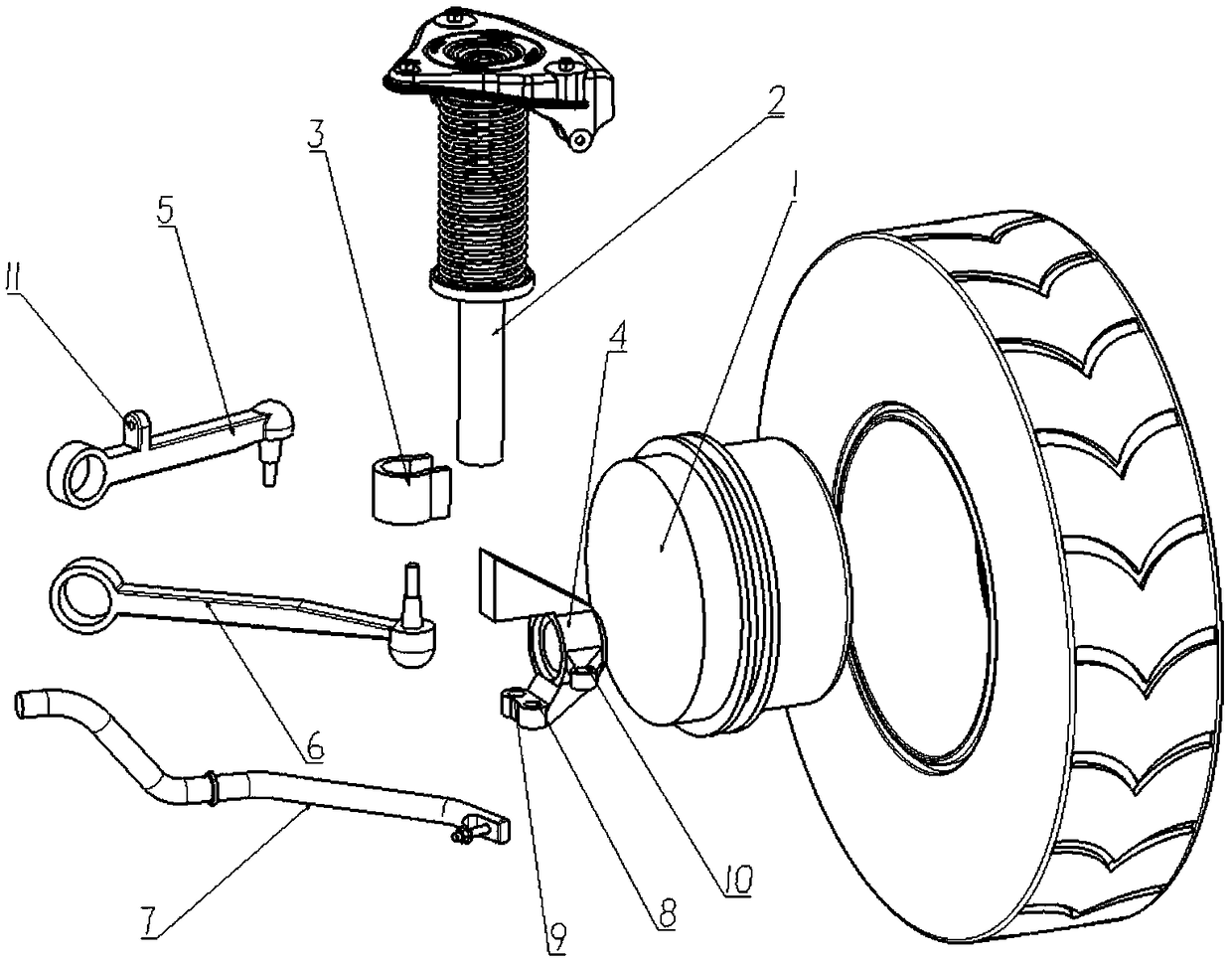
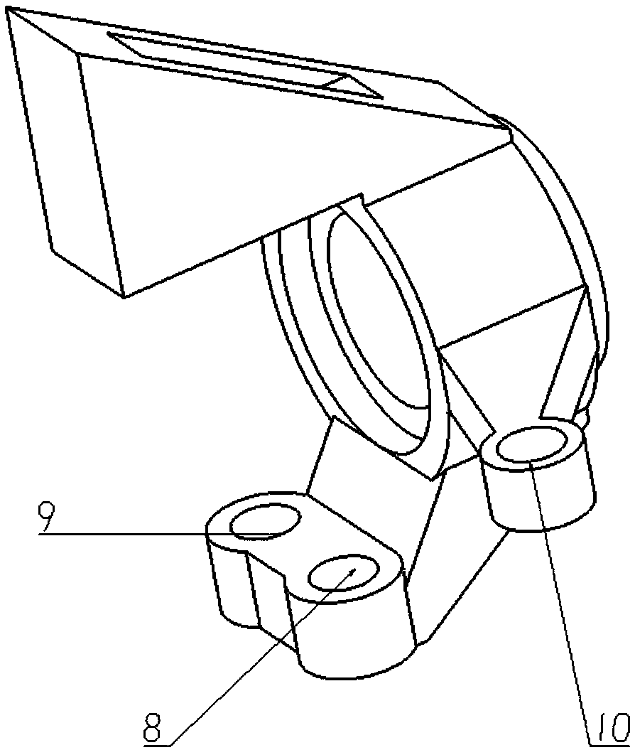
[0021] like figure 1 and 2 As shown, the present invention provides a suspension angle assembly of an in-wheel motor driven electric vehicle, which includes a in-wheel motor 1, a shock absorber bracket assembly 2, a steering knuckle 3 and a stabilizer bar assembly 7, and the steering knuckle 4 Fixedly connected to the wheel hub motor 1, the shock absorber bracket 2 assembly is fixedly connected to the upper end of the steering knuckle 4 through the connecting bracket 3; it also includes a front lower swing arm 5 and a rear lower swing arm 6, both of which are in the shape of connecting rods. There are two positioning holes at the lower end of the joint 4; the ball at one end of the front lower swing arm 5 is fixedly connected with the ball pin. One of the positioning holes is fixedly connected, and the other end is fixed on the vehicle frame through a universal joi...


PUM


Abstract

The invention relates to a suspension angle assembly of an electric vehicle driven by a hub motor. The suspension angle assembly comprises a front lower swing arm and a rear lower swing arm which areboth shaped like connecting rods, wherein two position-fixing holes are arranged at the lower end of a steering knuckle; one end of the front lower swing arm is fixedly connected to one of the position-fixing holes at the lower end of the steering knuckle by a ball pin and the other end of the front lower swing arm is fixed to a vehicle frame by a universal joint; one end of the rear lower swing arm is fixedly connected to the other one of the position-fixing holes at the lower end of the steering knuckle by another ball pin and the other end of the rear lower swing arm is fixed to the vehicleframe by another universal joint; a stabilizer bar assembly is fixedly connected to the front lower swing arm and the other end of the stabilizer bar assembly is mounted on the vehicle frame; and theintersection point of extension lines of straight lines on which the front lower swing arm and the rear lower swing arm are positioned and the pivot point of a ball hinge which fixes and connects theupper end of a shock absorber support assembly with the vehicle frame are the kingpin axis of the vehicle. The problems that the size of lower swing arms of a MacPherson strut suspension affects thesteering operability and that the increase of the unsprung weight affects the driving comfort can be solved.

Description

technical field [0001] The invention relates to a hub motor vehicle suspension system, in particular to a suspension angle assembly of a hub motor driven electric vehicle. Background technique [0002] With the development of electric vehicles and the popularization of in-wheel motor applications, new requirements are put forward for the matching and operability of the vehicle system. Especially the operating stability and driving comfort of the car, among which the operating stability of the car has a crucial impact on driving safety, and the driving comfort is to ensure that passengers have a good driving experience, especially when electric vehicles are installed with hub motors. The problems of increased vehicle mass, increased unsprung mass, and reduced suspension installation layout space that emerged later imposed more stringent conditions on the design and installation of the suspension rod system. [0003] The closest existing technology of the present invention is...

Claims


Application Information

Patent Timeline
Patent Type & Authority Applications(China)
IPC IPC(8): B60G7/00B60G13/00B60G21/055B60K7/00
CPCB60G7/00B60G13/003B60G21/055B60K7/0007
Inventor 庄晔魏健楠王其光张勇
Owner JILIN UNIV
Learn More