Roof heat preservation system structure

A thermal insulation system and thermal insulation layer technology, which is applied to roofs, roof coverings, building roofs, etc., can solve the problems of large workload, many construction steps, and accelerated aging of thermal insulation materials, so as to improve and reduce time cost and economic cost Material waste and labor loss, and the effect of improving fireproof and waterproof functions

Pending Publication Date: 2018-11-30
北京利泰装饰工程有限公司
View PDF5 Cites 5 Cited by
  • Summary
  • Abstract
  • Description
  • Claims
  • Application Information

AI Technical Summary

Problems solved by technology

[0004] 1. A lot of labor is required on the waterproof layer. After the waterproof layer is completed, there will be many follow-up construction steps, which will inevitably damage the waterproof layer, and it is not easy to find after the waterproof layer is damaged. Leakage will only be found after the roof is completed, so that the leak point is not easy to find , and it is necessary to remove the reinforced concrete protective layer, thermal insulation layer and roof tiles during the repair, the workload is relatively large and the maintenance is difficult;
[0005] 2. It needs to use a lot of steel bars and concrete. As we all know, these two materials are not environmentally friendly materials, and they are also high-energy-consuming materials. They have relatively large environmental pollution and run counter to the concept of building environmental protection.
[0007] 1. The roof is very prone to water leakage, because the water strip is directly nailed to the waterproof material. Although the SAB self-adhesive coil is resistant to nail penetration and self-closing to the nail penetration material, there will be a lot of construction in the future for the waterproof layer. Steps, the construction personnel step on the water strips in large numbers, which will cause the water strips to slip, which will inevitably tear the waterproof material and cause permanent irreversible damage;
[0008] 2. The waterproof material of SAB itself has relatively large require

Method used


Image

  • Roof heat preservation system structure
  • Roof heat preservation system structure
  • Roof heat preservation system structure

Examples


Embodiment

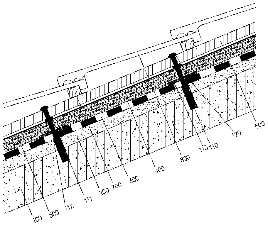
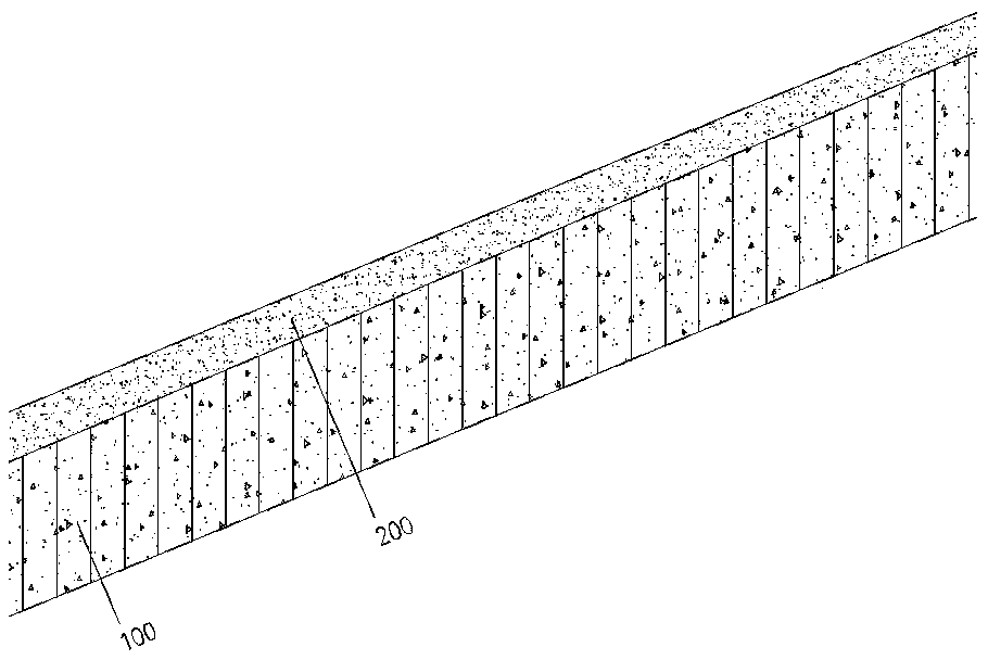
[0045] like figure 1 As shown, the roof insulation system structure of the present invention includes a reinforced concrete base layer 100 and a mortar leveling layer 200 laid on the reinforced concrete base layer 100. On the mortar leveling layer 200, a line planting bar 110, a waterproof layer 300, and a thermal insulation layer are sequentially arranged The layer 400, the protective layer 500 and the downstream strip 600, the tile hanging strip 700 is laid on the downstream strip 600, the roof tile 800 is hung on the hanging tile strip 700, and the downstream strip 600 is fixed on the protective layer 500 through the metal planting bar structure and leveled , the protective layer 500 is a mortar protective layer or a protective layer covered with an easy-to-roll material

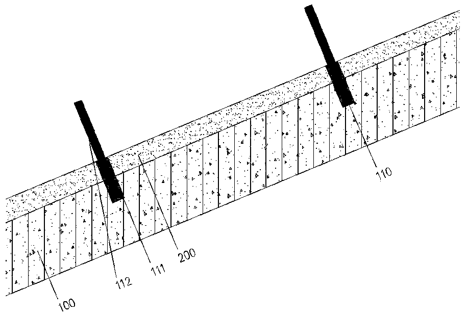
[0046] like image 3 and Figure 7As shown, the metal planting bar structure includes a metal planting bar 110 and a fixing member 120. One end of the metal planting bar 110 is fixed on the reinforced c...


PUM

PropertyMeasurementUnit
Thicknessaaaaaaaaaa
Thicknessaaaaaaaaaa
Thicknessaaaaaaaaaa

Abstract

The invention aims to disclose a roof heat preservation system structure, which comprises a reinforced concrete base layer and a mortar leveling layer laid on the reinforced concrete base layer, wherein pay-off embedded steel bars, a waterproof layer, a heat preservation layer, a protective layer and counter battens are sequentially arranged on the mortar leveling layer, roof battens are laid on the counter battens, hanging roof tiles are arranged on the roof battens, the counter battens are fixed on the protective layer through a metal bar structure and are levelled, and the protective layeris a mortar protective layer or an easy-to-coil material covering protective layer. Compared with the prior art, the roof heat preservation system structure has good waterproof effect, is suitable forconstruction of various modeling slope roofs, has good heat preservation performance, less wet operation and strong air convection, has effects of energy conservation and environment protection, greatly reduces the use of non-renewable or less-renewable resources, is an advocacy of green building engineering and achieves the objective of the present invention.

Description

technical field [0001] The invention relates to a roof structure, in particular to a roof insulation system structure. Background technique [0002] There are two main types of sloping roofs in existing construction projects. Although they are widely used, they both have relatively large defects. Either the resource consumption is relatively large, which is contrary to the environmental protection of the construction industry currently advocated, or a series of construction quality such as water leakage are prone to occur. question. [0003] One is to make a waterproof layer on the leveling layer, a thermal insulation layer and a reinforced concrete protective layer on the waterproof layer, and a water strip on the protective layer perpendicular to the direction of the roof ridge. . However, its disadvantages are: [0004] 1. A lot of labor is needed on the waterproof layer. After the waterproof layer is completed, there are many subsequent construction steps, which will ...

Claims


Application Information

Patent Timeline
IPC IPC(8): E04D11/02E04D13/16
CPCE04D11/02E04D13/1606
Inventor 王永青
Owner 北京利泰装饰工程有限公司
Why Eureka
Try Eureka