
Time discriminating circuit system

A circuit system and time identification technology, applied in the field of laser measurement, can solve problems such as increased circuit complexity, oscillation, high-speed comparator output instability, etc., to achieve the effects of controlling drift error, overcoming attenuation, and avoiding false triggering

Pending Publication Date: 2018-11-30
上海星秒光电科技有限公司
View PDF5 Cites 1 Cited by
  • Summary
  • Abstract
  • Description
  • Claims
  • Application Information

AI Technical Summary

Problems solved by technology

The constant ratio timing time identification method divides the echo signal into two channels for delay and attenuation respectively, and enters the positive and negative poles of the high-speed comparator to capture the signal jump, which can reduce the time identification error caused by the amplitude change of the laser pulse signal; but among them Before the delay signal arrives, the attenuation signal is equal to the delay signal amplitude, which will easily cause the output of the high-speed comparator to be unstable or even oscillate; and this method usually needs to add a bias circuit to ensure that the two signals are not equal to each other before the comparison time , which also increases the complexity of the circuit
The constant-ratio constant-ratio time discrimination method is suitable for pulse signals with the same rise time but different amplitudes, and there will be certain errors for pulse signals with different amplitudes and different rise times

Method used


Image

  • Time discriminating circuit system
  • Time discriminating circuit system

Examples


Embodiment Construction

[0020] In order to make the object, technical solution and advantages of the present invention clearer, the present invention will be further described in detail below with reference to the accompanying drawings and embodiments.

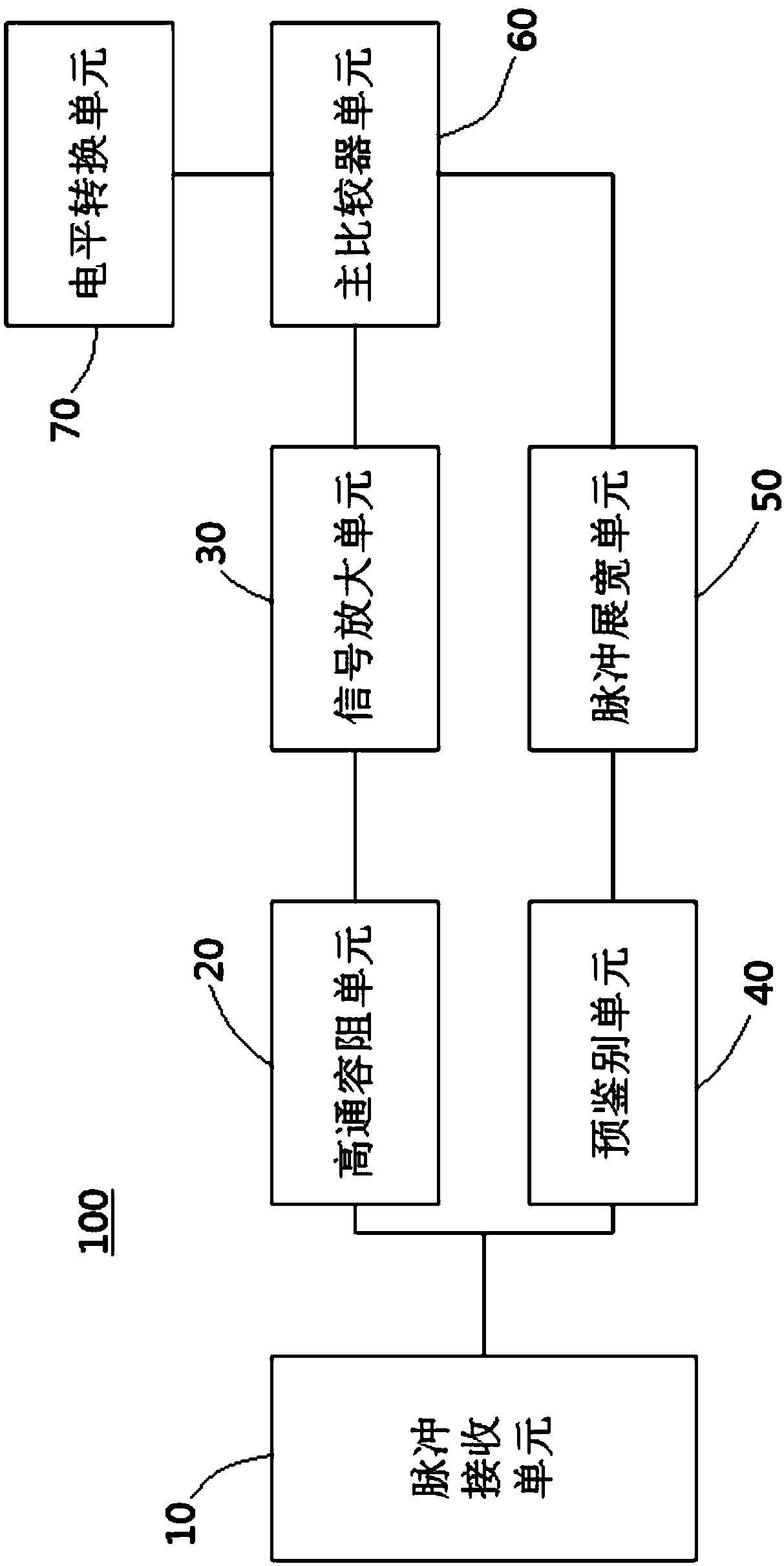
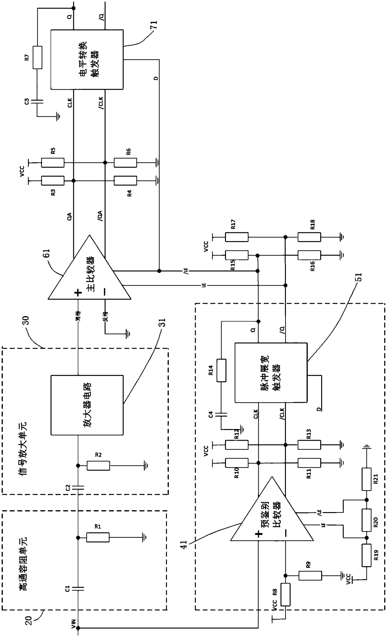
[0021] see figure 1 One embodiment of the present invention provides a time identification circuit system 100, which can be applied in the field of laser measurement technology, such as laser radar, laser fuze, laser guidance and other specific fields. The timing discrimination circuit system 100 includes a pulse receiving unit 10 , a high-pass capacitive resistance unit 20 , a signal amplifying unit 30 , a pre-discriminating unit 40 , a pulse stretching unit 50 , a main comparator unit 60 , and a level conversion unit 70 . The pulse receiving unit 10 is electrically connected with the high-pass capacitive resistance unit 20 and the pre-identification unit 40, the high-pass capacitive resistance unit 20 is electrically connected to the main comparato...


PUM


Abstract

The invention discloses a time discriminating circuit system, which comprises a pulse receiving unit, a high-pass capacitive-resistance unit, a signal amplification unit, a main comparator unit and alevel conversion unit which are electrically connected in sequence, wherein the pulse receiving unit is used for receiving a laser echo pulse signal of a ranging laser pulse and converting the laser echo pulse signal into a unipolar pulse signal; the high-pass capacitive-resistance unit is used for converting the unipolar pulse signal into a bipolar signal; an extreme point of the unipolar pulse signal is converted into a zero point of the bipolar signal and is used as a timing point; the signal amplification unit is used for amplifying the bipolar signal; the main comparator unit is used forcapturing a time jump point based on the amplified bipolar signal and generating a main output signal; and the level conversion unit is used for generating and outputting a time pulse for triggering timing stop time of laser ranging based on the main output signal generated by the main comparator unit.

Description

technical field [0001] The invention relates to the technical field of laser measurement, in particular to a time identification circuit system, which can be used in specific fields such as laser radar, laser fuze, and laser guidance. Background technique [0002] Pulsed laser ranging technology uses laser pulse beams to perform non-contact measurement of long-distance targets, and obtains distance information by measuring the time of flight (TOF) of laser pulses. Its general working process is: the time when the laser generates the initial pulse is determined as the initial moment of the flight time (denoted as T start ); the end pulse generated by the laser is detected by the avalanche photodiode and converted into a photoelectric signal. The trailing edge of the flat signal is determined as the end moment of the flight time (denoted as T stop ), and then calculate T stop with T start The difference between (T stop -T start ), the difference is taken as the flight ti...

Claims


Application Information

Patent Timeline
IPC IPC(8): G01S7/487
CPCG01S7/487
Inventor 刘鹏张帅陈杰
Owner 上海星秒光电科技有限公司
Learn More