Method for qualitatively calibrating pinhole camera by utilizing single ball and asymptotic line

A pinhole camera and asymptote technology, applied in the field of computer vision, can solve problems such as only estimation and error accumulation, and achieve the effects of simple production, improved calibration accuracy, and improved accuracy

Active Publication Date: 2018-11-30
YUNNAN UNIV
View PDF6 Cites 4 Cited by
  • Summary
  • Abstract
  • Description
  • Claims
  • Application Information

AI Technical Summary

Problems solved by technology

First, the intersection of the two principal axes of the ellipse is used to determine the principal point and the aspect ratio. Next, the focal length is determined according to the coefficient equation of the ellipse. However, this method will cause errors to accumulate and can only estimate part of the camera intrinsic parameters

Method used


Image

  • Method for qualitatively calibrating pinhole camera by utilizing single ball and asymptotic line
  • Method for qualitatively calibrating pinhole camera by utilizing single ball and asymptotic line
  • Method for qualitatively calibrating pinhole camera by utilizing single ball and asymptotic line

Examples


Embodiment

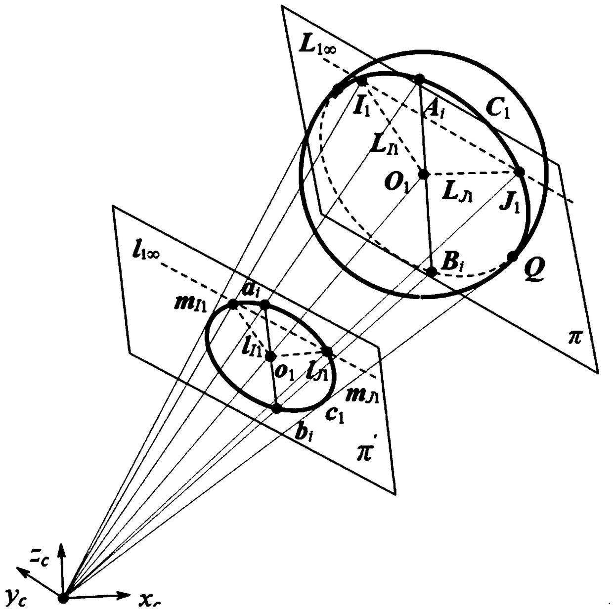
[0074] The invention proposes a method for linearly determining internal parameters of a pinhole camera by using a space sphere as a target. The experimental template structural schematic diagram that the present invention adopts is as figure 1 shown. The implementation of the present invention will be described in more detail with an example below.

[0075] The experimental template used in the calibration of pinhole cameras based on spheres in space is a sphere in space, such as figure 1 As shown, the ball is marked as Q. Utilize the method among the present invention to calibrate the pinhole camera for experiment, concrete steps are as follows:

[0076] 1. Fit image boundary and target curve equation

[0077] The image size used in the present invention is 1038×1048. Take three experimental images of the target with a pinhole camera, read the images, use the Edge function in Matlab to extract the pixel coordinates of the edge points of the target image, and use the lea...


PUM


Abstract

The invention relates to a method for qualitatively calibrating a pinhole camera by utilizing a single ball and an asymptotic line, characterized in that a ball element is utilized only. Firstly, pixel coordinates of target image edge points are extracted from three images and a ball image equation is obtained by adopting least square fitting. On the basis of the obtained ball image equation, an asymptotic line of a ball image is solved. The asymptotic line of the ball image is namely a polar line of an image of a circular point about the ball image, thus an image of a circle center is determined according to a polarity principle, orthogonal end points can be obtained by virtue of the image of the circle center, and the three images provide six groups of orthogonal end points. Finally, intrinsic parameters of the camera are solved by utilizing constraints of the orthogonal end points on an absolute conic image. The method comprises the following specific steps: fitting a target projection equation, estimating the asymptotic line of the ball image, determining the orthogonal end points, and solving the intrinsic parameters of the pinhole camera.

Description

technical field [0001] The invention belongs to the field of computer vision and relates to a method for solving the internal parameters of a parabolic catadioptric camera by using the properties of a sphere and a parallel circle tangent in space. Background technique [0002] The central task of computer vision is to understand images, and its ultimate goal is to enable computers to have the ability to recognize three-dimensional environmental information through two-dimensional images. This ability will not only enable the machine to perceive the geometric information of objects in a three-dimensional environment including shape, posture, motion, etc., but also describe, store, recognize and understand them. Camera calibration is to determine the mapping relationship from a three-dimensional space point to its two-dimensional image point, which is an essential step in many computer vision applications. In order to determine this mapping process, it is necessary to establi...

Claims


Application Information

Patent Timeline
Patent Type & Authority Applications(China)
IPC IPC(8): G06T7/80
CPCG06T7/80
Inventor 赵越杨丰澧汪雪纯
Owner YUNNAN UNIV
Why Eureka
Try Eureka