
A rotor position weight observer for permanent magnet synchronous motor without auxiliary signal injection

A permanent magnet synchronous motor, rotor position technology, applied in the direction of electronic commutator, control generator, motor control, etc., can solve the problems of increasing the iron loss and copper loss of the motor, noise, safety hazards, etc., to improve the control performance , expand the application field, improve the effect of accuracy

Active Publication Date: 2020-04-24
HARBIN INST OF TECH
View PDF3 Cites 0 Cited by
  • Summary
  • Abstract
  • Description
  • Claims
  • Application Information

AI Technical Summary

Problems solved by technology

[0003] At present, vector control is the most commonly used control technology for permanent magnet motors, but it requires decoupling of motor rotor position information, and the installation of position sensors not only increases the cost, but also reduces the reliability of the system, so sensorless control technology has become a research hotspot
[0004] In the field of zero and low speed, the most commonly used sensorless control technology for permanent magnet synchronous motors is the high-frequency signal injection method, but the high-frequency injection method additionally increases the response current component, and has a high alternating frequency, which will increase the motor iron at the same time. loss and copper loss
Not only that, the high-frequency current inside the motor will also bring problems of electromagnetic compatibility and noise. Such high-frequency components will interfere with the surrounding electromagnetic equipment. In severe cases, the electromagnetic equipment will malfunction and cause safety hazards.
Limited by the switching loss of the inverter, the frequency of the injected signal is generally within 10kHz, within the range of human hearing, which will generate sharp and harsh noises, which severely limits its application in some industrial occasions and household frequency conversion electrical appliances.

Method used


Image

  • A rotor position weight observer for permanent magnet synchronous motor without auxiliary signal injection
  • A rotor position weight observer for permanent magnet synchronous motor without auxiliary signal injection
  • A rotor position weight observer for permanent magnet synchronous motor without auxiliary signal injection

Examples


Embodiment Construction

[0045] The technical solutions of the present invention will be described in detail and clearly below in conjunction with the accompanying drawings of specific embodiments of the present invention. Apparently, the described specific implementation is only a part of the present invention. Based on the specific implementation in the present invention, all other implementations obtained by those of ordinary skill in the art without creative work belong to the present invention scope of protection.

[0046] It should be noted that, in the case of no conflict, specific implementations and features in the implementations of the present invention may be combined with each other.

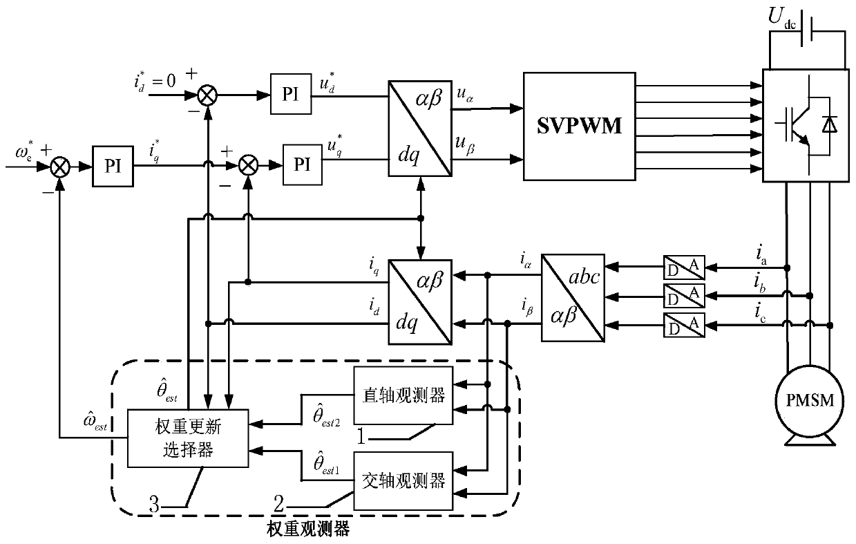
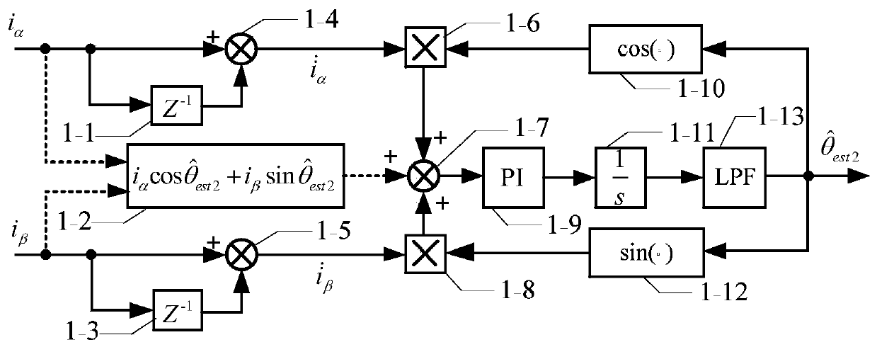
[0047] The following will further illustrate the present invention with reference to the accompanying drawings and specific embodiments of the present invention, but it is not intended as a limitation of the present invention. to combine Figure 1-Figure 7 Describe this specific embodiment, a permanent ma...


PUM


Abstract

The invention provides an auxiliary signal injection-free permanent magnet synchronous motor rotor position weight observer. On the basis of an existing permanent magnet synchronous motor vector controller, a straight axis observer, a quadrature axis observer and a weight updating selector. In the weight observer, the straight axis observer and the quadrature axis observer estimates the position of a rotor at the same time; a straight axis current and a quadrature axis current are continuously detected through a weight updating algorithm to judge whether a permanent magnet synchronous motor isoperated under a low load condition or a heavy load condition; a weight coefficient is adjusted in real time, and the rotor estimation positions output by the two observers are weighted to obtain a final rotor estimation position; and the auxiliary signal injection-free permanent magnet synchronous motor rotor position weight observer is applied to sensorless control of the permanent magnet motor.

Description

technical field [0001] The invention relates to a sensorless controlled permanent magnet synchronous motor rotor position observer, in particular to a permanent magnet synchronous motor rotor position weight observer without auxiliary signal injection, which belongs to the field of motor control. Background technique [0002] In recent years, great breakthroughs have been made in the manufacturing technology of power switching devices such as thyristors and IGBTs, and the capacity and frequency have been improved. At the same time, the research on the speed regulation strategy of AC motors has been continuously improved, and the AC speed regulation system has gradually become the mainstream in the field of electric drives. The permanent magnet synchronous machine has the advantages of high power density, high moment-to-inertia ratio, high power factor and good speed regulation performance, and has been widely used in elevators, electric vehicles, air-conditioning compressors...

Claims


Application Information

Patent Timeline
Patent Type & Authority Patents(China)
IPC IPC(8): H02P6/18H02P21/13H02P21/18H02P21/24
CPCH02P6/18H02P21/13H02P21/18H02P21/24H02P2203/09H02P2207/05
Inventor 张国强王高林毕广东赵楠楠匡俊耀徐殿国
Owner HARBIN INST OF TECH
Learn More