Activated carbon treatment system for improving waste heat utilization rate and denitration rate and using method thereof

A treatment system and activated carbon technology, applied in the field of flue gas purification, can solve the problems of poor denitration effect and low heat utilization efficiency.

Active Publication Date: 2018-12-07
ZHONGYE-CHANGTIAN INT ENG CO LTD
View PDF5 Cites 15 Cited by
  • Summary
  • Abstract
  • Description
  • Claims
  • Application Information

AI Technical Summary

Problems solved by technology

[0011] Aiming at the problems of low heat utilization efficiency and poor denitrification effect when flue gas is treated by activated carbon treatment system in the prior art, the present invention provides an activated carbon treatment system that improves waste heat utilization rate and denitrification rate. Heat exchangers are installed before the adsorp

Method used


Image

  • Activated carbon treatment system for improving waste heat utilization rate and denitration rate and using method thereof
  • Activated carbon treatment system for improving waste heat utilization rate and denitration rate and using method thereof
  • Activated carbon treatment system for improving waste heat utilization rate and denitration rate and using method thereof

Examples


Embodiment approach

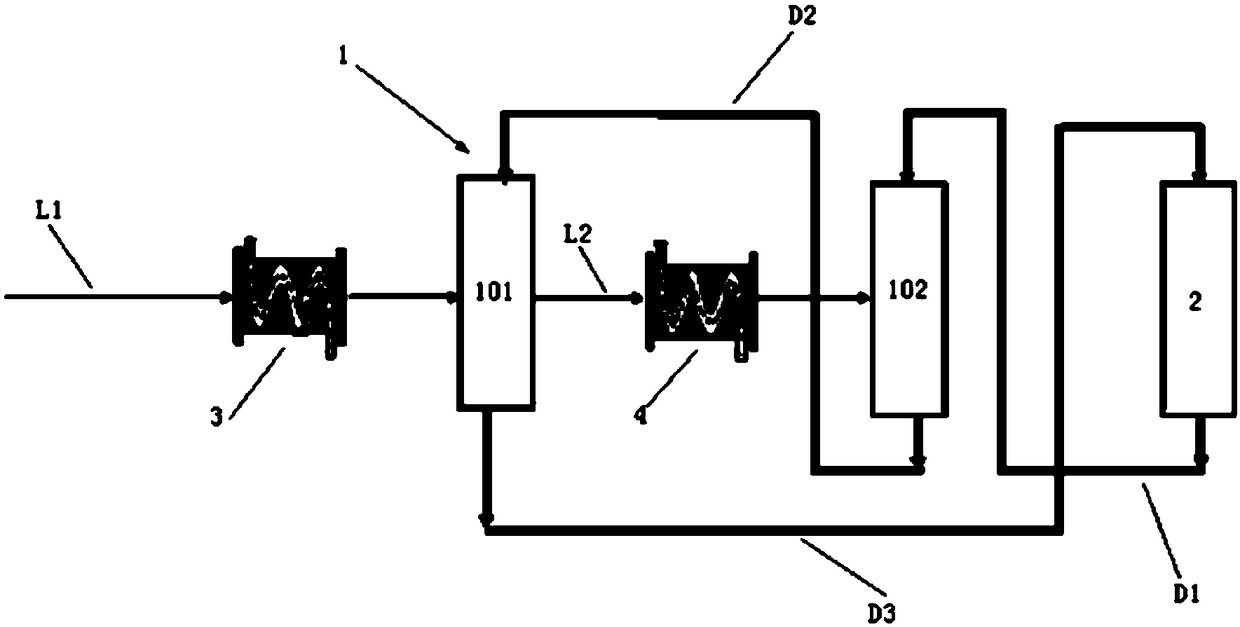
[0142] According to the first embodiment provided by the present invention, an activated carbon treatment system for improving waste heat utilization rate and denitrification rate is provided.

[0143] An activated carbon treatment system for improving waste heat utilization rate and denitrification rate, the activated carbon treatment system includes an activated carbon adsorption tower 1 and an activated carbon desorption tower 2 . The activated carbon adsorption tower 1 is a two-stage adsorption tower, including a first-stage adsorption tower 101 and a second-stage adsorption tower 102 . The activated carbon treatment system also includes raw flue gas delivery pipeline L1, first flue gas heat exchanger 3, second flue gas heat exchanger 4, primary treatment flue gas delivery pipeline L2, first activated carbon delivery device D1, second activated carbon delivery Device D2, the third activated carbon delivery device D3.

[0144] Wherein: the original flue gas delivery pipeli...

Embodiment 1

[0167] Such as figure 1 As shown, an activated carbon treatment system that improves waste heat utilization rate and denitrification rate, the activated carbon treatment system includes an activated carbon adsorption tower 1 and an activated carbon desorption tower 2. The activated carbon adsorption tower 1 is a two-stage adsorption tower, including a first-stage adsorption tower 101 and a second-stage adsorption tower 102 . The activated carbon treatment system also includes raw flue gas delivery pipeline L1, first flue gas heat exchanger 3, second flue gas heat exchanger 4, primary treatment flue gas delivery pipeline L2, first activated carbon delivery device D1, second activated carbon delivery Device D2, the third activated carbon delivery device D3.

[0168] Wherein: the original flue gas delivery pipeline L1 is connected to the flue gas inlet of the first-stage adsorption tower 101 . The flue gas outlet of the first-stage adsorption tower 101 is connected to the flue...

Embodiment 2

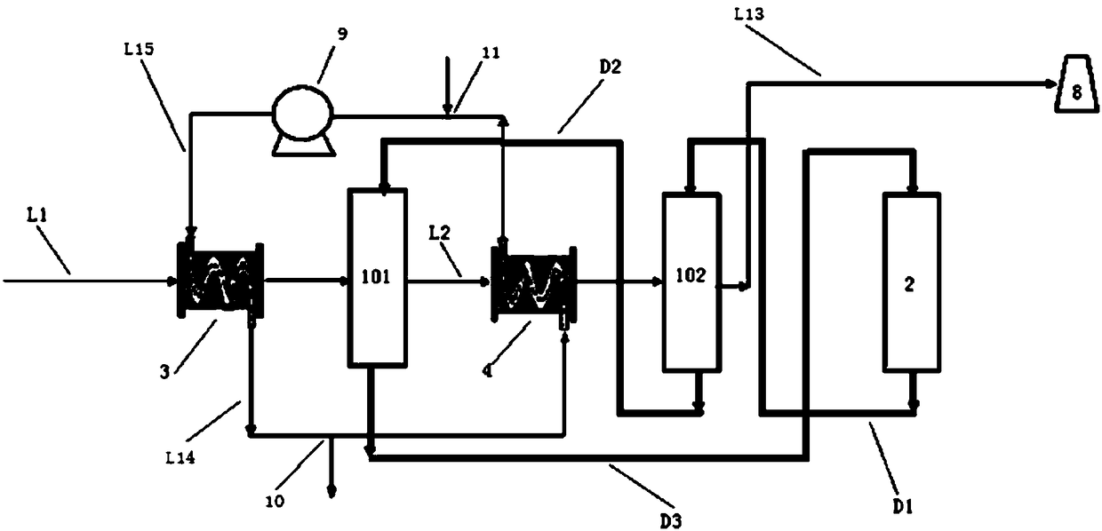
[0170] Such as figure 2As shown, Example 1 is repeated, except that the gas outlet of the first flue gas heat exchanger 3 is connected to the gas inlet of the second flue gas heat exchanger 4 through the first heat exchanger medium delivery pipe L14. The gas outlet of the second flue gas heat exchanger 4 is connected to the gas inlet of the first flue gas heat exchanger 3 through the second heat exchanger medium delivery pipe L15. A fan 5 is provided on the first heat exchanger medium delivery pipeline L3. A fan 9 is provided on the first heat exchanger medium delivery pipeline L3 and / or the second heat exchanger medium delivery pipeline L4 .


PUM


Abstract

The invention provides an activated carbon treatment system for improving waste heat utilization rate and denitration rate and a using method thereof. Heat exchangers are separately disposed before flue gas is input into a first-stage adsorption column and a second-stage adsorption column, the temperature of the flue gas entering the first-stage adsorption column and the second-stage adsorption column is controlled, thereby ensuring the temperature of desulfurization and denitration. The activated carbon treatment system utilizes high-temperature flue gas (about 150-170 DEG C) after a main exhaust blower, adopts a mode of heat exchange, artificially controls the temperature of the flue gas entering the first-stage adsorption column and the second-stage adsorption column, and enables the efficiency of removal of SO<2> and NO<x>; and the utilization rate of the high-temperature flue gas after the main exhaust blower is increased, and the temperature of the flue gas entering a desulfurization tower and a denitration tower is controlled to improve the efficiency of desulfurization and denitration.

Description

technical field [0001] The invention relates to an activated carbon treatment system, in particular to a flue gas desulfurization and denitrification system for improving waste heat utilization rate and denitrification rate, and belongs to the field of flue gas purification. Background technique [0002] After the sintering flue gas passes through the main exhaust fan, the discharge temperature is about 110-170 ° C, which contains SO 2 , NO x , dust, dioxins, heavy metals and other pollutants, and the activated carbon flue gas purification technology is just suitable for the sintering flue gas temperature emission range, which can realize the synergistic and efficient purification of multiple pollutants, and can simultaneously remove a variety of pollutants on a set of equipment Pollutants, achieving by-product SO 2 The utilization of resources, and this technology has the advantages of high pollutant removal efficiency, basically no consumption of water resources, and no ...

Claims


Application Information

Patent Timeline
IPC IPC(8): B01D53/02B01D53/06F28F27/02
CPCB01D53/02B01D53/06B01D2253/102B01D2257/40B01D2258/0283B01D2259/40022B01D2259/40088B01D2259/4009F28F27/02Y02A50/20
Inventor 李俊杰魏进超康建刚
Owner ZHONGYE-CHANGTIAN INT ENG CO LTD
Why Eureka
Try Eureka