Eureka AIR delivers breakthrough ideas for toughest innovation challenges, trusted by R&D personnel around the world.

Passivating device for high-temperature Fischer-Tropsch synthesis of waste catalyst

A waste catalyst, Fischer-Tropsch synthesis technology, used in catalyst protection, physical/chemical process catalysts, preparation of liquid hydrocarbon mixtures, etc. The effect of lowering temperature and reducing catalyst activity

Pending Publication Date: 2018-12-07
YANKUANG ENERGY R&D CO LTD
View PDF0 Cites 0 Cited by
  • Summary
  • Abstract
  • Description
  • Claims
  • Application Information

AI Technical Summary

Problems solved by technology

The catalyst of the Fischer-Tropsch synthesis reaction is mainly in a reduced state, so the catalyst needs to be reduced before it is added to the synthesis reactor. As the reaction progresses, the activity of some catalysts decreases or is damaged. Therefore, it is necessary to regularly discharge and add some catalysts online to ensure that the catalyst Concentration, activity and selectivity, because the metals in the spent catalyst are still in a reduced state in large quantities, and the nature is relatively active, and it is easy to undergo an oxidation reaction when exposed to the air, causing spontaneous combustion, which brings safety hazards to the operating device and the transportation of the spent catalyst. Therefore, Catalyst passivation treatment must be carried out before the spent catalyst is sent out of the boundary area
The traditional catalyst passivation is generally discharged into the slag pool and then fished out after passivation with water, which will cause catalyst pollution and component loss, which is not conducive to catalyst recovery; if the direct passivation with water vapor is easy to cause catalyst agglomeration due to water vapor condensation, affecting the catalyst discharge, the present invention overcomes the above shortcomings, is more conducive to the recycling of catalysts, and also avoids sewage discharge

Method used


Image

  • Passivating device for high-temperature Fischer-Tropsch synthesis of waste catalyst
  • Passivating device for high-temperature Fischer-Tropsch synthesis of waste catalyst

Examples


Embodiment

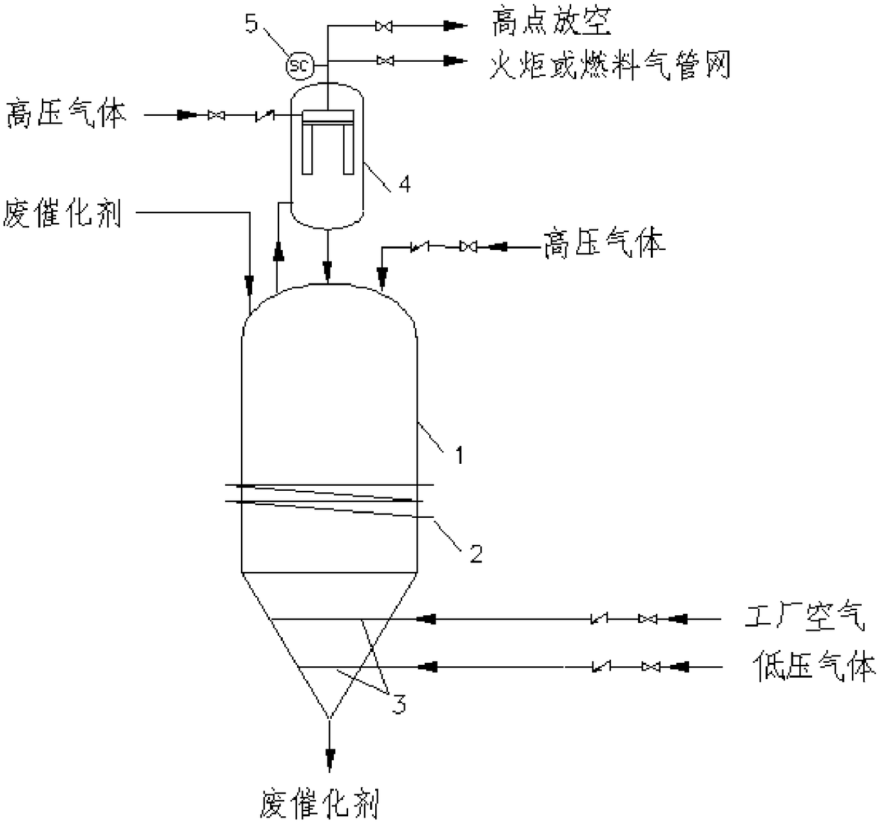
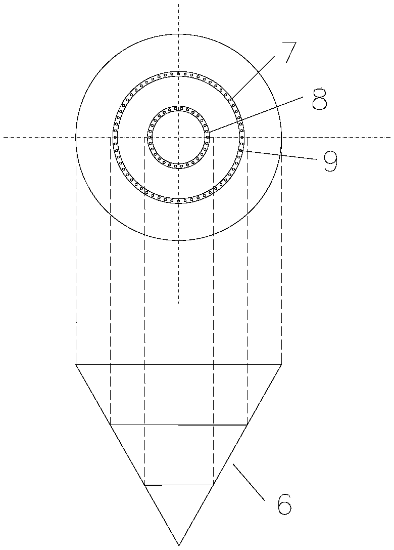
[0029] A high-temperature Fischer-Tropsch synthesis waste catalyst passivation device, its structure is as follows figure 1 As shown, it includes a spent catalyst collection tank 1 and a gas-solid separator 4 connected to the top of the spent catalyst collection tank 1 . The inner angle of the cone bottom 6 of the spent catalyst collection tank 1 is 60°, and the cone bottom is provided with a two-layer gas distributor 3, such as figure 2shown. Counting from top to bottom, what passes into the first layer of gas distribution pipe 7 is factory air, and passes into low-pressure gas in the second layer of gas distribution pipe 8, such as low-pressure nitrogen can be passed into, on the above-mentioned distribution pipe evenly distributed with small Hole 9. A cooling coil 2 is arranged outside the collection tank, and the heat exchange medium in the tube is cooling water. High-pressure nitrogen is installed on the top of the waste catalyst collection tank, and the pressure of t...


PUM


Abstract

The invention relates to a passivating device for high-temperature Fischer-Tropsch synthesis of a waste catalyst. The passivating device comprises a waste catalyst collecting tank (1) and a gas-solidseparator (4) connected to the top of the waste catalyst collecting tank (1); a heat exchange tube (2) is arranged on the inner side and / or outer side of the waste catalyst collecting tank (1); a conebase is arranged on the bottom of the waste catalyst collecting tank; one or multiple layers of gas distributors (3) are arranged on the cone base; an online oxygen analyzer (5) is arranged on a gasoutlet pipeline of the gas-solid separator. The passivating device is capable of reducing temperature and reactivity of the catalyst, replacing the reactant gas and hydrocarbons carried by the catalyst and avoiding the danger caused by the contact between a reactant gas and passivating air. Compared with the prior art, the passivating device is capable of efficiently and cleanly performing passivating treatment on the waste catalyst, is beneficial to the recycling of the catalyst and is capable of avoiding sewage discharge.

Description

technical field [0001] The invention relates to a passivation device, in particular to a passivation device for high-temperature Fischer-Tropsch synthesis spent catalysts. Background technique [0002] Fischer-Tropsch synthesis is the core of indirect coal liquefaction technology. Fischer-Tropsch synthesis converts synthesis gas (CO+H2) into hydrocarbons and water through iron-based or cobalt-based catalysts. According to the reaction temperature, Fischer-Tropsch synthesis is further divided into low-temperature Fischer-Tropsch synthesis and high-temperature Fischer-Tropsch synthesis. The high-temperature Fischer-Tropsch synthesis has a reaction temperature of 300-400°C and a reaction pressure of 2.0-5.0 MPa, using a circulating fluidized bed or a fixed fluidized bed. In the reactor, the catalyst adopts a melting method iron-based catalyst or a precipitation method iron-based catalyst. The catalyst of the Fischer-Tropsch synthesis reaction is mainly in a reduced state, so t...

Claims


Application Information

Patent Timeline
IPC IPC(8): B01J33/00C10G2/00
CPCC10G2/342B01J33/00C10G2300/705
Inventor 孙启文岳建平刘继森吴建民董良滕强
Owner YANKUANG ENERGY R&D CO LTD
Why Eureka
Eureka Blog
Learn More