Continuous conveying double-face air drying device for eel roasting and hot air drying method
A technology of an air drying device and a conveying device, which is applied in the directions of drying solid materials, drying goods processing, and drying gas arrangement, can solve the problems affecting the efficiency and effect of drying, poor processing continuity, and uneven drying, etc., to improve the overall flow rate The effect of stability, simple structure and easy operation
- Summary
- Abstract
- Description
- Claims
- Application Information
AI Technical Summary
Problems solved by technology
Method used
Image
Examples
Embodiment 1
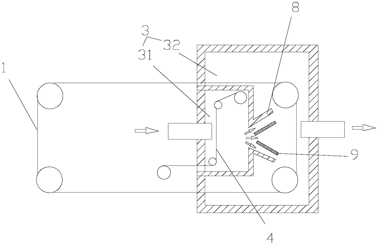
[0047] Such as figure 1 As shown, this embodiment discloses a continuous conveying double-sided air-drying device for grilled eel processing, including a conveying device 1, a blowing device, an air-drying bin 3, and a filtering device 4. The conveying device 1 is used to feed the eel pieces to be air-dried to the In the air-drying warehouse 3, the eel piece in the air-drying warehouse 3 is air-dried after the hot air blown out from the blowing device is filtered through the filter device 4 .
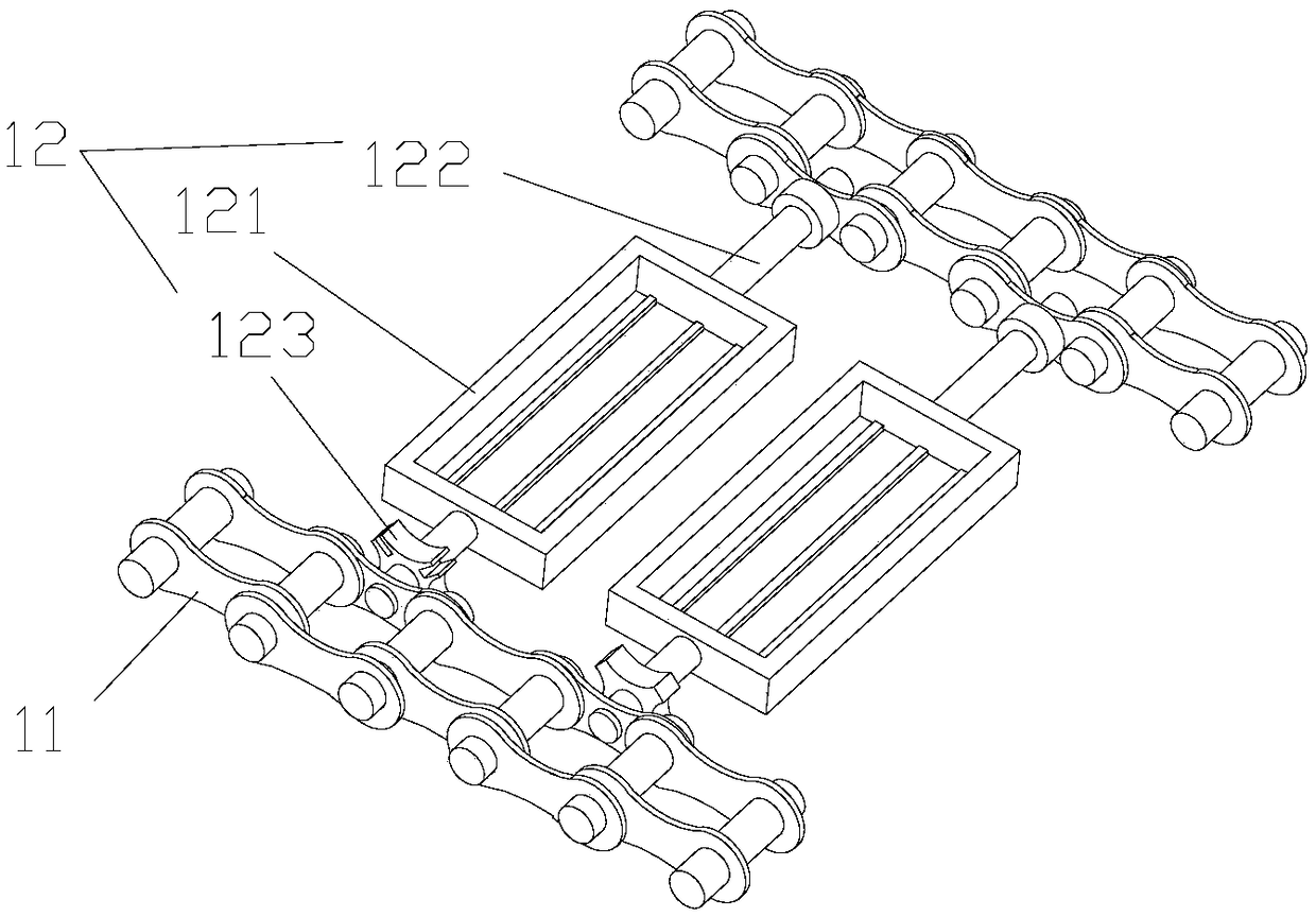
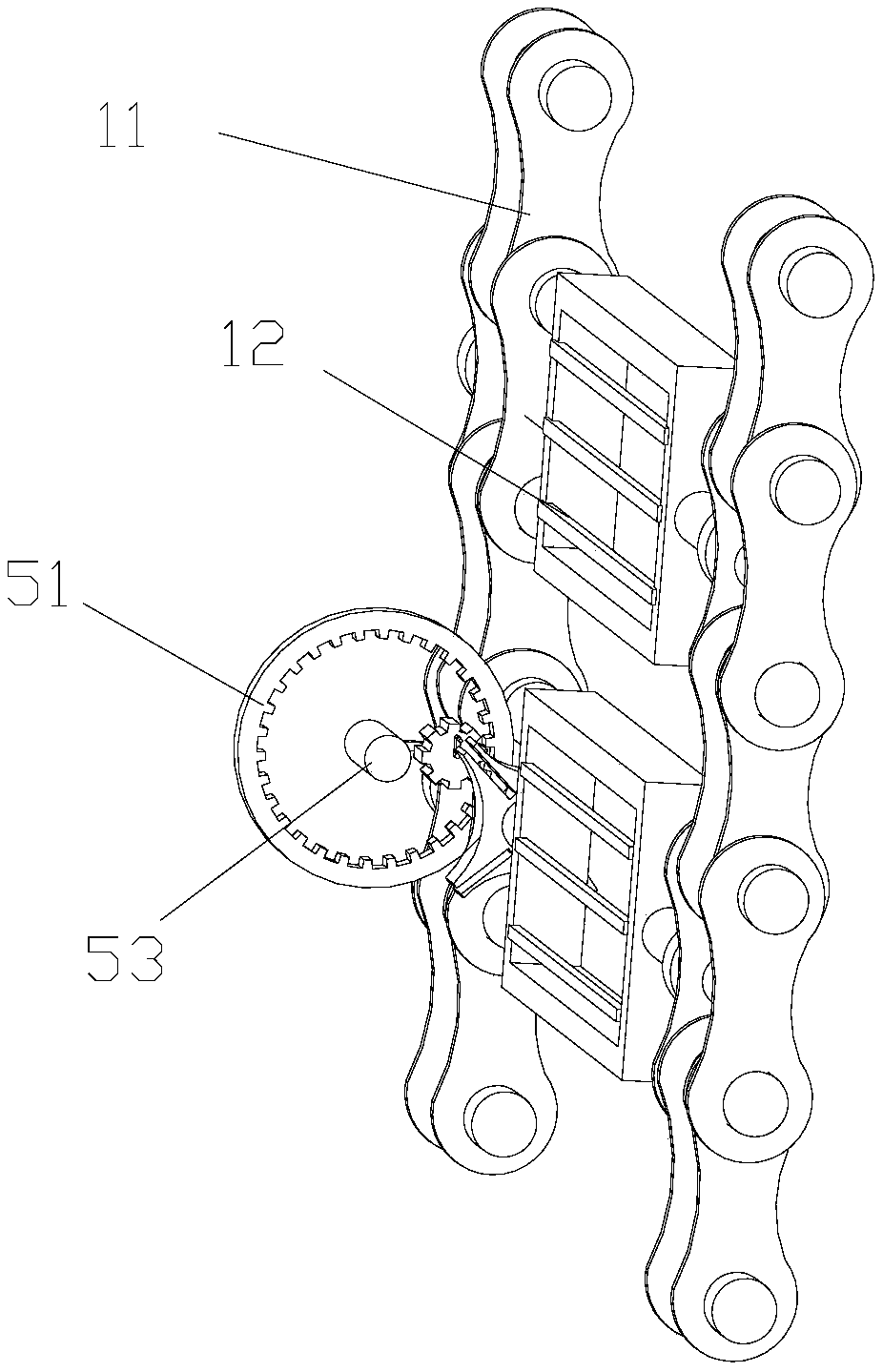
[0048] Such as Figure 2-4 As shown, the conveying device 1 includes two sets of conveyor belts 11 arranged in parallel, and a grilled eel loading device 12. The grilled eel loading device 12 is connected between the two sets of conveyor belts 11, and a plurality of grilled eel loading devices 12 are transported along the conveyor belts 11. Orientation interval setting. The grilled eel loading device 12 includes a net box 121 , a connecting shaft 122 , and a four-corner rotating part ...
Embodiment 2
[0054] Such as Figure 5-6 As shown, the difference between the present embodiment and the foregoing embodiments is that the net box 121 includes a bottom frame 1211 and a cover plate 1212, and the bottom frame 1211 and the cover plate 1212 are closed around and hollowed out in the middle. A plurality of first support bars 1213 are provided at intervals, and positioning rods 1214 are provided on the first support bars 1213, and the positioning rods 1214 are needle-shaped. One end of the cover plate 1212 is hinged to one end of the bottom frame 1211 through a pivot shaft 1217 , and the other end of the cover plate 1212 can be closed on the other end of the bottom frame 1211 . A plurality of second support bars 1216 are arranged at intervals in the hollow area of the cover plate 1212 .
[0055] A positioning block 1218 is disposed on the pivot shaft 1217, and a thread groove is opened on the positioning block 1218. A positioning slot 12111 is provided on the bottom frame 121...
Embodiment 3
[0059] Such as Figure 5-6 As shown, the difference between this embodiment and the above-mentioned embodiments lies in that the other end of the cover plate 1212 and the other end of the bottom frame 1211 are attracted or engaged with each other. The first support bar 1213 and the second support bar 1216 are distributed in a warp and weft dislocation.
[0060] Because the other end of the cover plate 1212 and the other end of the bottom frame 1211 are attracted or engaged with each other, when the cover plate 1212 is closed on the bottom frame 1211, further, the gap between the cover plate 1212 and the bottom frame 1211 is raised. Combined tight effect. Since the first support bar 1213 and the second support bar 1216 are dislocated in warp and latitude, the upper and lower sides of the eel block are respectively subject to longitudinal and transverse limiting effects. Such a network-like limiting structure further improves the limiting effect of the eel block. .
PUM
 Abstract
Description
Claims
Application Information
 - R&D
- Intellectual Property
- Life Sciences
- Materials
- Tech Scout
- Unparalleled Data Quality
- Higher Quality Content
- 60% Fewer Hallucinations
Browse by: Latest US Patents, China's latest patents, Technical Efficacy Thesaurus, Application Domain, Technology Topic, Popular Technical Reports.
© 2025 PatSnap. All rights reserved.Legal|Privacy policy|Modern Slavery Act Transparency Statement|Sitemap|About US| Contact US: help@patsnap.com


