Object-oriented non-condensable gas-containing vapor condensation visualization experiment device

An object-oriented technology for steam condensation, applied in the direction of measuring devices, material condensation, instruments, etc., can solve the problems of complex system, lack of heating device on the wall of the experimental chamber, unsuitable for low-pressure condensation, etc., achieve system simplification, high control accuracy, Experiment with a wide range of effects

Inactive Publication Date: 2018-12-07
ZHEJIANG UNIV
View PDF9 Cites 13 Cited by
  • Summary
  • Abstract
  • Description
  • Claims
  • Application Information

AI Technical Summary

Problems solved by technology

In the published literature, such as the experimental device in the article "Tianzhou No. 1 Space Condensation Experimental Device Ground Condensation Experiment", the experimental device can only condense pure steam on the surface of the condensation table, and the condensation table is placed in the liquid pool as a whole, which will make non- The condensing surface affects the condensing surface; the experimental device introduced in the article "Drop Condensation Strengthens the Condensation Heat Transfer Mechanism of Vapor Containing Non-Condensable Gas" uses the method of secondary condensation of excess steam to control the pressure in the experimental chamber , the system is complex and not suitable for low-pressure condensation; the condensation experimental device used in the article "Jumping-droplet-enhanced condensation on scalable superhydrophobic nanostructured surfaces" does not have the function of surface heating recovery, and can only perform condensation of pure steam outside the tube. The control of the steam pressure in the experimental chamber is not accurate enough
Among the published patents, the "multifunctional heat transfer training device" disclosed in the patent document with the patent application number 201420533725.2 belongs to the chemical equipment for training, which is mainly used for training operations of different types of heat exchangers, and is not suitable for condensation Experimental research; the "single-tube in-pipe evaporation and condensation integrated experimental device" disclosed in the patent application number 200820155479.6 can only conduct single-tube in-pipe condensation experiments, and cannot perform visual analysis on the entire life cycle of droplets, and cannot carry out different Condensation experiment in the presence of condensate gas; although the "a wide subcooling and multi-component gas in-tube steam condensation heat transfer experimental system" disclosed in the patent document No. 201710168093.2 can perform multi-component gas in-tube condensation experiments, But also only for single tube; patent application number is 201210540382.8 disclosed in the patent document "Containing multi-component non-condensable gas steam condensation heat exchange experimental device" and patent application number is 201310084890.4 disclosed in the patent document "can realize Condensation heat transfer experimental device coupled with natural circulation and forced circulation" Due to the limitation of the structure of the experimental device, the experiment can only be carried out on the condensation process outside the standpipe at normal pressure and above pressure, and the wall of the experimental cavity lacks a heating device

Method used


Image

  • Object-oriented non-condensable gas-containing vapor condensation visualization experiment device
  • Object-oriented non-condensable gas-containing vapor condensation visualization experiment device
  • Object-oriented non-condensable gas-containing vapor condensation visualization experiment device

Examples


Embodiment Construction

[0026] Below in conjunction with accompanying drawing, the present invention is described in further detail:

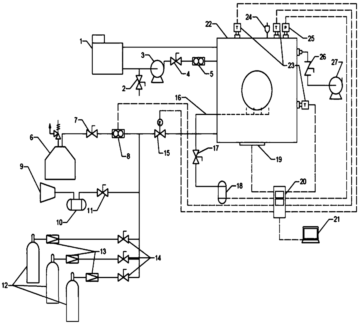
[0027] It mainly includes steam supply system, air supply system, other gas supply system, cooling water system, visual experiment body and data acquisition system.

[0028] In the steam supply system, the steam generator 6 generates steam, the initial steam flow is controlled by the steam flow regulating valve 7, and the vortex flowmeter 8 records the cumulative flow and the instantaneous flow.

[0029] The air supply system is composed of an air compressor 9 and an air storage tank 10. After the air is compressed, it enters the air storage tank 10 and enters the main air supply pipeline 32 after reaching the set pressure.

[0030] The other gas supply system consists of a high-pressure gas storage cylinder 12 and a pressure reducing valve 13 , and other gases enter the main gas supply pipeline 32 after being decompressed by the high-pressure gas storage cylinder 12 ...


PUM


Abstract

The invention discloses an object-oriented non-condensable gas-containing vapor condensation visualization experiment device. The device mainly comprises a steam supply system, an air supply system, other gas supply systems, a cooling water system, a visualized experimental body and a data acquisition system. Steam and a non-condensable gas component are produced by the steam supply system, the air supply system and the other gas supply systems. A main gas supply pipe is connected to an experimental cavity and is provided with an electric valve. The electric valve can adjust an opening degreeaccording to the negative feedback of the pressure in the experimental cavity to control the steam flow. Cooling water enters an experimental pipe section through a flowmeter under the action of a water pump, is subjected to heat exchange in the experimental pipe section and then is returned into a constant temperature water bath through a water return pipe. Before the experiment, a vacuum systemrealizes a high vacuum environment in the experimental chamber. The device realizes continuous measurement, analysis and visual observation of the condensation phenomenon under different steam pressures, different subcooling degrees, different non-condensable gas components and contents, and different surface structural characteristics.

Description

technical field [0001] The invention relates to an object-oriented visual experiment device for condensation of steam containing non-condensable gas, which belongs to the field of condensation heat transfer experiments. Background technique [0002] The condensation of water vapor is a common phase transition phenomenon in nature. Condensation of water vapor is a basic form of heat transfer, which can achieve high-efficiency heat transfer under small temperature differences. The condensation of water vapor is also an important link in energy conversion, environmental regulation, seawater desalination and thermal management systems. However, the condensation of water vapor in general industrial equipment is bound to be accompanied by a small amount of non-condensable gas, which is very unfavorable for heat exchange. Improving the heat and mass transfer effect of the condensation process of steam containing non-condensable gas can save natural resources, economic resources a...

Claims


Application Information

Patent Timeline
Patent Type & Authority Applications(China)
IPC IPC(8): G01N25/14
CPCG01N25/142
Inventor 范利武张天宇牟林巍李佳琦田帅奇冯飙俞自涛
Owner ZHEJIANG UNIV
Why Eureka
Try Eureka