
A method of reducing the leakage current of lithium ion capacitor

A technology of capacitors and lithium ions, which is applied in the field of electrochemical energy storage devices, can solve problems such as leakage current, achieve the effects of reducing leakage current, reducing leakage current, and increasing energy

Active Publication Date: 2020-08-11
INST OF ELECTRICAL ENG CHINESE ACAD OF SCI
View PDF5 Cites 0 Cited by
  • Summary
  • Abstract
  • Description
  • Claims
  • Application Information

AI Technical Summary

Problems solved by technology

In addition, lithium-ion capacitors generally use current collectors containing through-holes with a diameter of microns. The edges of these holes will inevitably have defects such as burrs. These burr defects will also form micro-short circuits and cause leakage currents. However, these defects are due to the Fluid processing can only be solved by optimizing the processing technology and equipment of the current collector; the trace amount of impurity ions contained in the electrode material, such as Fe 3+ , can shuttle between positive and negative electrodes, and also cause leakage current, both of which are not within the scope of the present invention

Method used

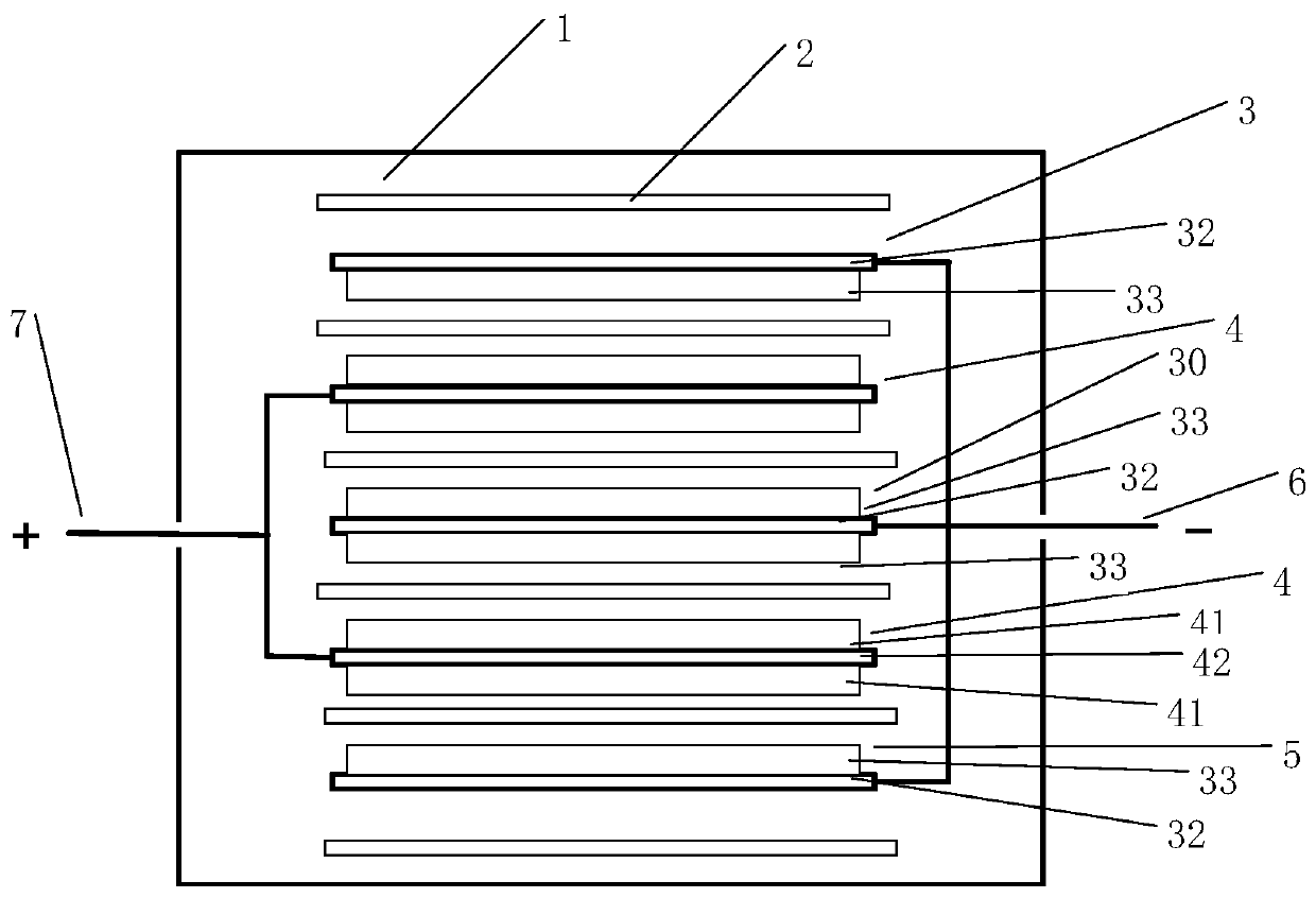

Image

  • A method of reducing the leakage current of lithium ion capacitor
  • A method of reducing the leakage current of lithium ion capacitor

Examples


Embodiment 1

[0036] Example 1 Preparation of lithium ion capacitor. The active material is the positive electrode of activated carbon, the active material is the negative electrode of hard carbon, and the electrolyte is 1mol / L LiPF 6 The solution, the solvent is a mixed solvent of ethylene carbonate, dimethyl carbonate and diethyl carbonate with a volume ratio of 1:1:1. Use CT2001A battery tester of Wuhan Landian Company, connect the negative electrode of the cell to the positive electrode of the tester, connect the negative electrode of the tester with the metal lithium electrode, pre-embed lithium on the negative electrode sheet by constant current method, and the amount of pre-embedded lithium is the negative electrode 80% of capacity. After the pre-intercalation of lithium is completed, the metal lithium electrodes are taken out and vacuum-sealed to obtain several lithium-ion battery capacitors. The charge and discharge test was carried out on the lithium ion capacitor in the voltage...

Embodiment 2

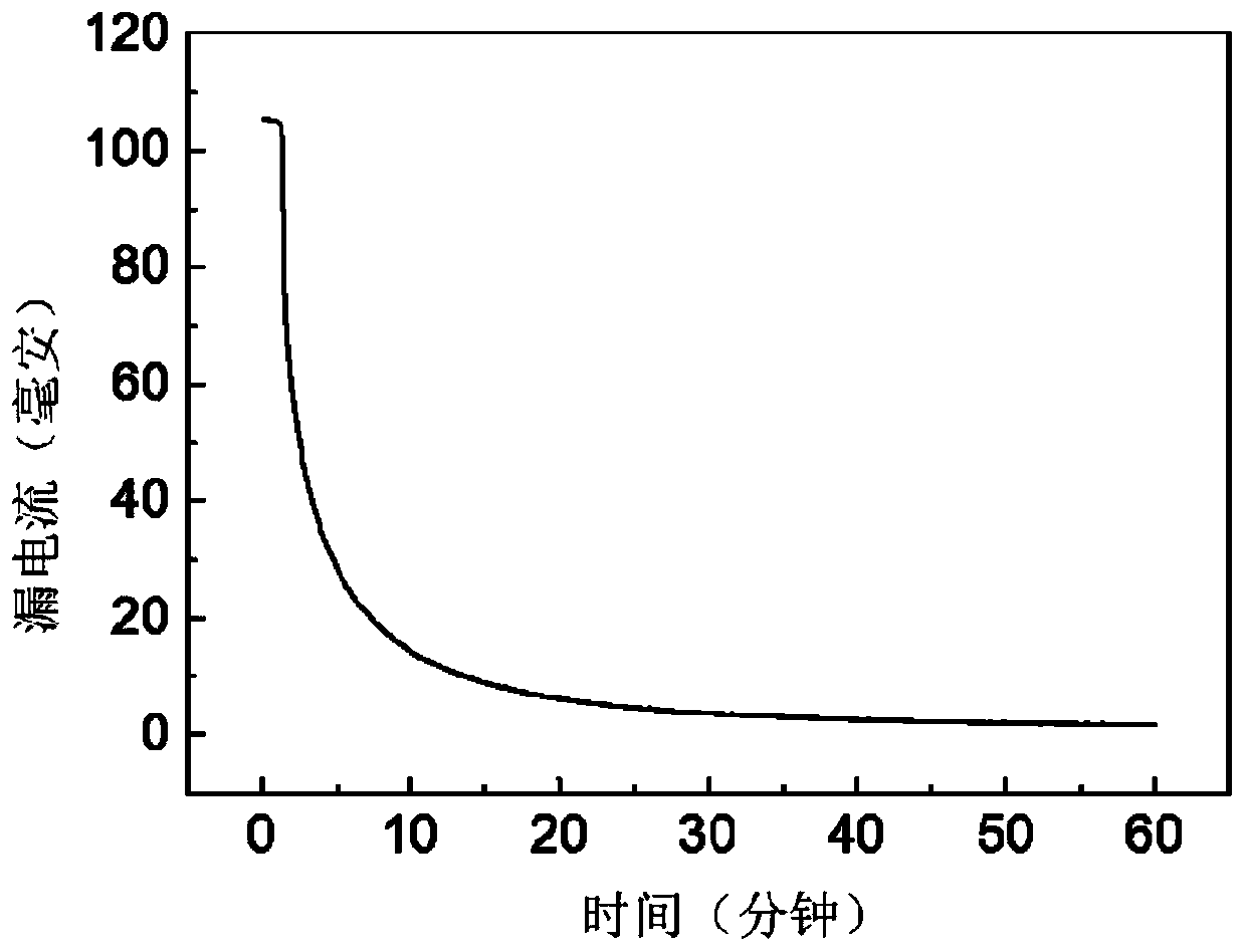
[0037] Example 2 Charge the lithium ion capacitor prepared in Example 1 to 4.15V (here, the current is 1C) with a constant current of 0.5A, charge it at a constant voltage of 4.15V for 180 minutes, discharge it to 2.0V, and then charge it at 0.5A The current is charged at a constant current to 4.0V, and then charged at a constant voltage at 4.0V for 1 hour to obtain a leakage current of 5mA. The test curve of the leakage current of lithium ion capacitor is as follows: figure 2 As shown, the abscissa is the time for testing the leakage current, and the ordinate is the current value during constant voltage charging at a rated voltage of 4.0V. The current value decreases exponentially with the constant voltage charging time, and the current at the end of charging is the leakage current.

Embodiment 3

[0038] Example 3 Charge the lithium-ion capacitor prepared in Example 1 to 4.2V at a constant current of 0.5A, charge at a constant voltage at 4.2V for 5 minutes, discharge to 2.0V, and charge at a constant current of 0.5A to 4.1V , and then charged at a constant voltage of 4.1V for 1 hour to obtain a leakage current of 6.2mA.


PUM


Abstract

The invention relates to a method for reducing leakage current of a lithium ion capacitor. The method comprises the steps of chagrining the lithium ion capacitor to voltage Ucharge by using constant current, applying constant voltage Ucharge to the positive electrode and the negative electrode of the lithium ion capacitor, and retaining for the constant voltage Ucharge for 5-180 minutes, wherein the relation of the applied constant voltage Ucharge and the rated voltage UR of the lithium ion capacitor satisfies that UR + 0.1 V <= Ucharge <= UR + 0.2 V. The leakage current of a lithium ion capacitor can be remarkably reduced.

Description

technical field [0001] The invention relates to a method for reducing the leakage current of a lithium ion capacitor, which belongs to electrochemical energy storage devices. Background technique [0002] Supercapacitor, also known as electrochemical capacitor, is a new type of energy storage element. It is between traditional capacitors and secondary batteries. Its capacity is much larger than traditional capacitors, and its high-rate charge and discharge performance is far superior to secondary batteries. . Supercapacitors can generally be divided into three types: electric double layer capacitors that physically store charges using the principle of electric double layers at the interface between electrodes and electrolytes; pseudocapacitors or hybrid capacitors that store charges using the principle of rapid redox reactions on the surface of electrode materials, And a battery capacitor in which an electric double layer capacitor and a secondary battery are combined insid...

Claims


Application Information

Patent Timeline
Patent Type & Authority Patents(China)
IPC IPC(8): H01G11/06H01G11/84G01R31/52
CPCG01R31/50H01G11/06H01G11/84Y02E60/13
Inventor 孙现众马衍伟张熊安亚斌
Owner INST OF ELECTRICAL ENG CHINESE ACAD OF SCI
Learn More