Low-voltage dynamic reactive compensation device for capacitor

A compensation device and capacitor technology, applied in reactive power compensation, circuit devices, reactive power adjustment/elimination/compensation, etc., can solve the problem of large harmonics in power supply and distribution systems, increasing the impact of harmonics on the power grid, and compensating loops Component damage and other problems, to achieve the effect of reducing power loss, saving more costs, and reducing line loss

Inactive Publication Date: 2018-12-07
铜陵市胜美达电子制造有限公司
View PDF5 Cites 0 Cited by
  • Summary
  • Abstract
  • Description
  • Claims
  • Application Information

AI Technical Summary

Problems solved by technology

[0003] 1. With the increase of nonlinear loads such as frequency converters, electric welding machines, and switching power supplies, the amount of harmonics generated in the power supply and distribution system is relatively large
[0004] 2. In the capacitance compensation cabinet of the suburban coal preparation plant, there is no series reactor at the front end of the capacitor, which causes harmonic amplification, and the switching element capacitor has insufficient current resistance, which causes failures easily
At this time, the harmonic voltage will form a strong current on the series circuit and directly flow through the compensation capacitor bank, causing the capacitor to fail quickly due to overcurrent, and at the same time increase the impact of harmonics on the power grid
[0008] 3. The temperature grade of the capacitor is B grade, the temperature grade is low, and there is no heat dissipation device such as an axial flow fan, the capacitance value of the capacitor decays quickly when the temperature is high, and the resonance point shifts after the capacitance value decays, which is easy to generate resonance, so that the compensation circuit becomes low. Impedance, inflow of harmonic current, causing damage to compensation circuit components

Method used


Image

  • Low-voltage dynamic reactive compensation device for capacitor
  • Low-voltage dynamic reactive compensation device for capacitor
  • Low-voltage dynamic reactive compensation device for capacitor

Examples


Embodiment Construction

[0026] In order to make the purpose, technical solutions and advantages of the embodiments of the present invention clearer, the technical solutions in the embodiments of the present invention will be clearly and completely described below in conjunction with the drawings in the embodiments of the present invention. Obviously, the described embodiments It is a part of embodiments of the present invention, but not all embodiments. Based on the embodiments of the present invention, all other embodiments obtained by persons of ordinary skill in the art without creative efforts fall within the protection scope of the present invention.

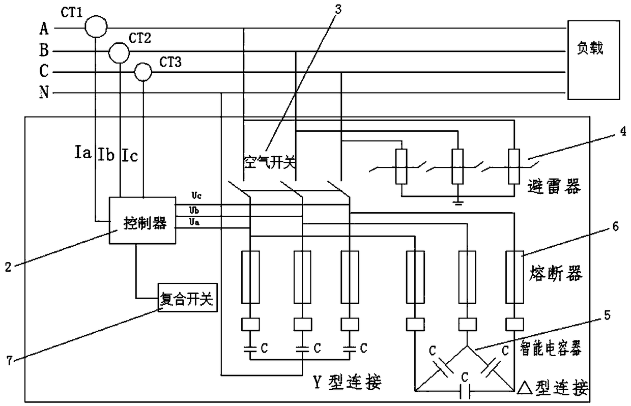
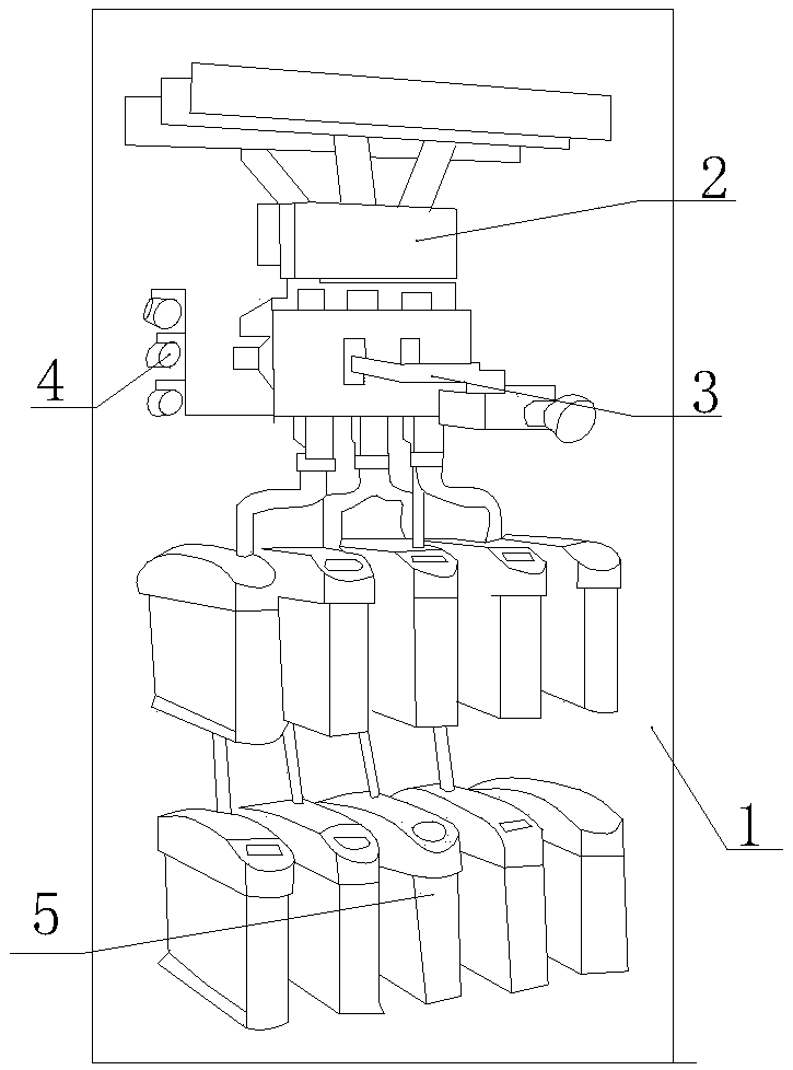
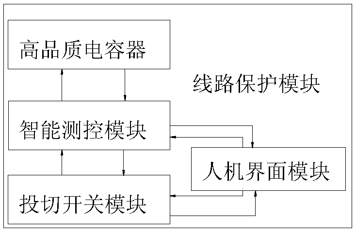
[0027] refer to Figure 1 to Figure 3 As shown, the present invention provides a low-voltage dynamic reactive power compensation device for capacitors, including a cabinet 1, a controller 2, an air switch 3, a lightning arrester 4, an intelligent capacitor 5, a fuse 6 and a composite switch 7, and the controller 1 Connected in parallel to the out...


PUM


Abstract

The invention provides a low-voltage dynamic reactive compensation device for a capacitor. The low-voltage dynamic reactive compensation device comprises a cabinet body, a controller, an air switch,a lightning arrester, an intelligent capacitor, a fuse and an intelligent capacitor, wherein the controller is connected to the output end of a power system in parallel, the air switch is sequentiallyconnected with the lightning arrester, the fuse and the intelligent capacitor, and the controller is connected with a composite switch, and an intelligent measurement and control module on the intelligent capacitor is communicated with a high-quality capacitor and a switching switch module. A circuit protection module is respectively communicated with the high-quality capacitor, the intelligent measurement and control module, the switching switch module and a human-computer interface module, and the man-machine interface module is connected with the switching switch module and the intelligentmeasurement and control module. The controller is used for analyzing the data information inside an electric system, a compensation branch and the intelligent capacitor and giving out capacitor switching on / off, various protection early warning, actions and other operation instructions. According to the scheme, dynamic reactive compensation can be realized for a 0. 4kV-level power grid, and the power supply quality is improved.

Description

technical field [0001] The invention relates to the technical field of electric low-voltage distribution network, in particular to a low-voltage dynamic reactive power compensation device for capacitors. Background technique [0002] As a large number of non-linear loads such as modern power electronic equipment are connected to the power grid, the power supply quality of the power grid is seriously affected. Among them, a large number of applications of various power electronic switching devices and frequent fluctuations in loads are the main sources of interference, resulting in a series of bad influences. Grid voltage quality is usually measured by indicators such as stability, symmetry and sine. [0003] 1. With the increase of nonlinear loads such as frequency converters, electric welding machines, and switching power supplies, the amount of harmonics generated in the power supply and distribution system is relatively large. [0004] 2. In the capacitance compensation...

Claims


Application Information

Patent Timeline
Patent Type & Authority Applications(China)
IPC IPC(8): H02J3/18
CPCH02J3/1821Y02E40/30
Inventor 夏斌
Owner 铜陵市胜美达电子制造有限公司
Why Eureka
Try Eureka