
Driving circuit of semiconductor devices in high-power converter and working method thereof

A driving circuit and semiconductor technology, which is applied to output power conversion devices, emergency protection circuit devices, electrical components, etc., can solve the problems of asynchronous switching action in response time, high difficulty in engineering application promotion, and poor dynamic current sharing effect. Achieve the effect of simplifying signal line routing, improving current sharing, and ensuring synchronization

Inactive Publication Date: 2018-12-07
西安翌飞核能装备股份有限公司
View PDF13 Cites 4 Cited by
  • Summary
  • Abstract
  • Description
  • Claims
  • Application Information

AI Technical Summary

Problems solved by technology

Parallel drive of semiconductor devices can also be realized, but the inconsistency of the response time of each drive expansion board directly leads to asynchronous switching actions of parallel semiconductor devices, making the dynamic current sharing effect poor
[0004] Chinese patent ZL201610624444.1 "An IGBT Parallel Current Sharing Circuit and Its Control Method" discloses an IGBT parallel current sharing circuit and its control method. Finally, by adjusting the driving signal time and driving signal amplitude of the semiconductor device to achieve current sharing, the method is relatively complicated and equivalent to increasing the delay in the forward channel of the control, which limits the performance of the converter to a certain extent
And engineering application promotion is more difficult

Method used


Image

  • Driving circuit of semiconductor devices in high-power converter and working method thereof

Examples


Embodiment Construction

[0021] In order to make the object, technical solution and advantages of the present invention clearer, the present invention will be further described in detail below through specific implementation methods in conjunction with the accompanying drawings. Apparently, the described examples are some examples, but not all examples of the present invention. Based on the embodiments of the present invention, all other embodiments obtained by persons of ordinary skill in the art without making creative efforts belong to the protection scope of the present invention.

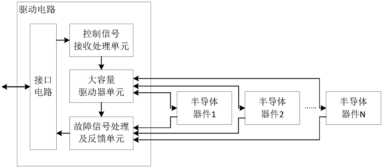
[0022] Such as figure 1 As shown, a high-power converter drive circuit of the present invention includes: a control signal receiving and processing unit, a large-capacity driver unit, and a fault signal processing and feedback unit, wherein: the control signal receiving and processing unit is used to convert an external drive signal Generate 2 complementary drive signals with dead zones and transmit them to the large-...


PUM


Abstract

The invention discloses a driving circuit of semiconductor devices in a high-power converter and a working method thereof. The driving circuit includes a control signal receiving and processing unit,a large-capacity driver unit and a fault signal processing and feedback unit. The control signal receiving and processing unit is used for generating two complementary driving signals with dead zone from an external driving signal and transmitting the driving signals to the large-capacity driver unit. The large-capacity driver unit is connected with the semiconductor devices, and is used for receiving and amplifying the driving signals sent by the control signal receiving and processing unit and sending the driving signals to the semiconductor devices, and obtaining the voltage value across the two ends of each semiconductor device and feeding the voltage values back to the fault signal processing and feedback unit. The large-capacity driver unit simultaneously drives one or more semiconductor devices, which ensures the synchronization of the driving signals of the semiconductor devices and improves the current sharing of the semiconductor devices. The currents and temperatures of thesemiconductor devices are monitored and protected on the basis, which ensures the safe and stable operation of the semiconductor devices of the high-power converter.

Description

technical field [0001] The invention belongs to the field of high-power converters, and in particular relates to a driving circuit of a semiconductor device of a high-power converter and a working method thereof. Background technique [0002] With the continuous increase of power load capacity, the application of high-power converters has been promoted. High-power converters with low performance requirements can be realized by a single high-current semiconductor device. However, high-current semiconductor devices cannot achieve high switching frequency due to their large junction capacitance, which limits the performance of the converter. High-power converters with high performance requirements can only be connected in parallel through multiple low-current semiconductor devices to achieve higher switching frequency to improve performance and expand capacity. The parallel connection of semiconductor devices requires that all semiconductor devices share current, and the degre...

Claims


Application Information

Patent Timeline
Patent Type & Authority Applications(China)
IPC IPC(8): H02M1/088H02H7/12
CPCH02H7/1206H02M1/088
Inventor 金岩阚啸叶宏勇
Owner 西安翌飞核能装备股份有限公司
Learn More