Balloon guide catheter

A catheter and balloon technology, applied in the field of medical devices, can solve the problems of limited curative effect and wide application, inaccessible catheter, short treatment time window, etc., and achieves good visibility, good flexibility and passability, and high blood supply. The effect of reconstruction rate

Inactive Publication Date: 2018-12-11
南京普微森医疗科技有限公司
View PDF0 Cites 22 Cited by
  • Summary
  • Abstract
  • Description
  • Claims
  • Application Information

AI Technical Summary

Problems solved by technology

The maximum inner diameter of the two is no more than 1.5mm, which cannot aspirate a larger vessel plug. At the same time, the outer diameter of the catheter is too large due to the balloon, and this type of catheter cannot enter the smaller distal vessel; cranial nerve One of the common treatment methods for blood vessels, intravenous thrombolytic therapy for ischemic stroke, has shortcomings such as a short treatment time window (within 4.5 hours) and a low revascularization rate (about 30%), which limits its curative effect and wide application
This requires that the balloon guide catheter and the suction catheter be inserted into the patient's diseased blood vessel segment at the same time, but the actual clinical operation requires a long operation time, and it increases the difficulty of the operation and delays the treatment, which brings great risks to the patient.

Method used


Image

  • Balloon guide catheter
  • Balloon guide catheter
  • Balloon guide catheter

Examples


Embodiment Construction

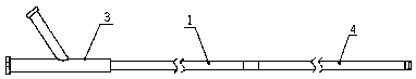
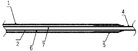
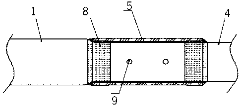
[0032] Such as Figure 1 to Figure 6 As shown, a balloon guide catheter includes a catheter, an outer tube, an inner tube and a suction tube, and the catheter is a composite tube composed of an outer tube 1, an inner tube 2, and a suction tube 4 located at the distal end of the catheter. And the outer layer of the distal end of the outer tube 1 is connected with an inflatable or contractible soft balloon 5; the annular cavity between the inner tube 2 and the outer tube 1 forms a balloon filling cavity 6; the distal end of the inner tube 2 and the suction tube The proximal ends of 4 are welded together; the inner cavity of the inner tube 2 and the inner cavity of the suction tube 4 are connected in series to form the guide cavity of the catheter, that is, the thrombus suction cavity 7; the proximal end of the catheter is provided with a Y-shaped joint 3, Y Type joint 3 comprises main inner hole and side hole along the horizontal direction; The main inner hole of Y-type joint 3 ...


PUM


Abstract

The invention provides a balloon guide catheter, and in particular relates to the technical field of medical apparatus and instruments. The catheter is a composite pipe composed of an outer tube, an inner tube, and a suction tube positioned at the far end of the catheter which are coaxial, and a flexible balloon capable of realizing the full or contraction state is connected to the outer layer ofthe far end of the outer tube; an annular cavity between the inner tube and the outer tube forms a balloon filling cavity; the far end of the inner tube is welded to the near end of the suction tube;an inner cavity of the inner tube is connected with the inner cavity of the suction tube in series to form a guide cavity of the catheter, namely, a thrombus suction cavity; a main inner hole of a Y-shaped joint communicates with the inner cavity of the inner tube to form a wire guide cavity and the thrombus suction cavity; and the axis of side holes of the Y-shaped joint and the axis of the maininner hole of the Y-shaped joint have intersection at the near end direction of the catheter to form an acute angle, and the side holes of the Y-shaped joint and a gap between the outer wall of the inner tube and the inner wall of the outer tube communicate to form the balloon filling cavity. For the balloon guide catheter, during the interventional treatment process, blood flow can be blocked, sothat small broken thrombus is prevented from blocking the far end, and meanwhile, large thrombus blocks at the near end can be sucked, so that the surgery effect is greatly improved.

Description

technical field [0001] The invention belongs to the technical field of medical devices, and in particular relates to a balloon guiding catheter. Background technique [0002] Thrombosis in cerebral blood vessels can lead to cerebral apoplexy (stroke), which is a common disease that seriously threatens human health. It is the third leading cause of death today and the first cause of long-term disability in adults. [0003] In order to solve the problem of thrombus blocking blood vessels, in the prior art, a thrombus suction catheter is usually used. By sending the catheter along the blood vessel to the thrombus site, negative pressure is directly applied to extract the thrombus, so that the blood vessel can re-establish hemodynamic force. However, during the operation, the thrombus often falls off and flows to the distal blood vessel, resulting in the failure of the aspiration operation, which may endanger the life of the patient in severe cases. In addition, when the cathet...

Claims


Application Information

Patent Timeline
Patent Type & Authority Applications(China)
IPC IPC(8): A61M25/10A61B17/22
CPCA61M25/10A61B17/22A61B2017/22067A61B2017/22079A61M2025/1052
Inventor 魏诗荣
Owner 南京普微森医疗科技有限公司
Why Eureka
Try Eureka