Miniature surface-mounted ignition resistor and preparation method thereof

An ignition resistor, surface-mounted technology, applied in the field of miniature surface-mounted ignition resistors and its preparation, can solve the problems of large package size, poor safety, high ignition current, etc., and achieve small package size, short ignition time, and high ignition current low effect

Active Publication Date: 2018-12-11
BEIJING MECHANICAL EQUIP INST
View PDF7 Cites 2 Cited by
  • Summary
  • Abstract
  • Description
  • Claims
  • Application Information

AI Technical Summary

Problems solved by technology

[0007] In view of the above analysis, the embodiment of the present invention aims to provide a miniature surface mount ignition resistor and its preparation method to solve the existing problems of excessive package size, high ignition current and poor safety

Method used


Image

  • Miniature surface-mounted ignition resistor and preparation method thereof
  • Miniature surface-mounted ignition resistor and preparation method thereof
  • Miniature surface-mounted ignition resistor and preparation method thereof

Examples


Embodiment 1

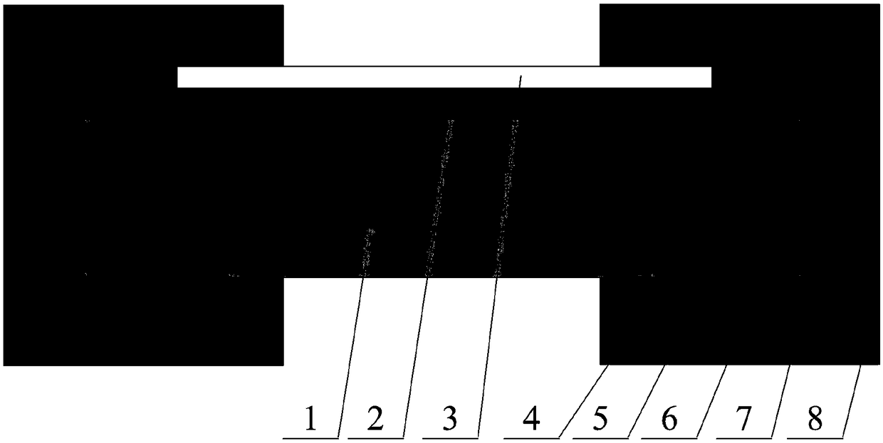
[0051] Such as figure 1 As shown, a specific embodiment of the present invention discloses a miniature surface-mounted ignition resistor, which includes a substrate 1, a resistive layer 2, a protective layer 3, a welding pad 4, and a surface-mounted ignition resistor. Connection layer 5, copper layer 6, nickel layer 7, tin layer 8.

[0052] The upper surface of the substrate 1 is provided with a resistance layer 2, and the two ends of the lower surface are respectively provided with pads 4; the two ends of the resistance layer 2 are electrically connected to the corresponding pads 4 through the surface and back lapping layers 5 respectively; the middle part of the upper surface of the resistance layer 2 is A protective layer 3 is also provided, and the two sides of the protective layer 3 are closely connected with the corresponding sides of the front and back lapping layers 5; Preferably, the thickness of the copper layer 6 is 0.01-0.03 mm, the thickness of the nickel layer 7...

Embodiment 2

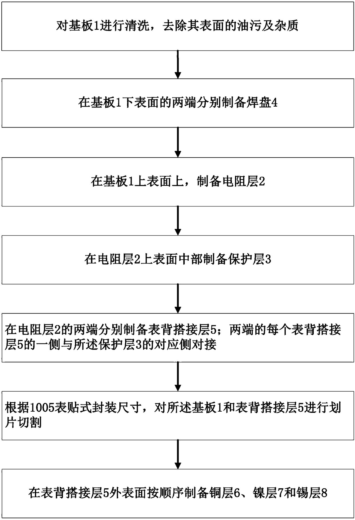
[0067] Such as image 3 As shown, a preparation method for preparing the miniature surface mount type ignition resistor described in Example 1 comprises the steps:

[0068] S1. Cleaning the substrate 1 to remove oil stains and impurities on its surface.

[0069] S2. Prepare pads 4 at both ends of the lower surface of the substrate 1 . Specifically, pads 4 are respectively prepared on both ends of the lower surface of the substrate 1 by at least one of a screen printing process and a sputtering coating process.

[0070] S3. On the upper surface of the substrate 1, a resistive layer 2 is prepared.

[0071] S4. In the middle of the upper surface of the resistance layer 2, a protective layer 3 is prepared. Specifically, the protection layer 3 is formed on the resistance layer 2 through a sputtering coating process.

[0072] S5. On both ends of the resistance layer 2, surface and back overlapping layers 5 are respectively prepared, and one end of each surface and back overlappi...


PUM


Abstract

The invention relates to a miniature surface-mounted ignition resistor and a preparation method thereof, belongs to the technical field of electric explosive devices, and solves the problems of oversize encapsulation dimension, relative too high firing current and poor safety in the prior art. The miniature surface-mounted ignition resistor disclosed by the invention comprises a base plate 1, a resistance layer 2, a protection layer 3, bonding pads 4, a surface back lap joint layer 5, a copper layer 6, a nickel layer 7 and a tin layer 8, wherein the resistance layer 2 is arranged on the uppersurface of the base plate 1; the bonding pads 4 are respectively arranged at two ends of the lower surface of the base plate 1; the two ends of the resistance layer 2 are connected with the corresponding bonding pads 4 through the surface back lap joint layer 5; the protection layer 3 is also arranged on the middle part of the upper surface of the resistance layer 2; the copper layer 6, the nickellayer 7 and the tin layer 8 are sequentially arranged at the outer surface of the surface back lap joint layer 5. The ignition resistor has the advantages that the encapsulation dimension is small; the ignition current is about 0.1A; the ignition time is smaller than 100mus; the firing energy is about 1mJ; the fast firing under the micro excitation can be realized; the safety performance is good;the prominent technical advantages are realized.

Description

technical field [0001] The invention relates to the technical field of electrical explosive devices, in particular to a miniature surface-mounted ignition resistor and a preparation method thereof. Background technique [0002] Existing miniature ignition resistors generally adopt a straight bridge structure, such as the metal thin film ignition resistors given in patents CN102927590A and CN105674808B. This straight bridge structure has the following disadvantages: [0003] 1) Although the ignition voltage is low (usually the ignition voltage is 4-5V), the required ignition current is very large (for example, 1.5A in CN105674808B), so the safety is poor; [0004] 2) The base material is generally made of Al 2 o 3 Ceramics, aluminum nitride, etc., Al 2 o 3 The thermal conductivity of ceramics is 24.7W / (m K), and the thermal conductivity of aluminum nitride is 270W / (m K). Because the thermal conductivity of the two is too high, it does not meet the heat insulation require...

Claims


Application Information

Patent Timeline
Patent Type & Authority Applications(China)
IPC IPC(8): F42C19/12
CPCF42C19/12
Inventor 高辉许诺罗杨黄伯超
Owner BEIJING MECHANICAL EQUIP INST
Why Eureka
Try Eureka