A lead foil leads out a conductive polymer aluminum electrolytic capacitor

A technology of conductive polymer and aluminum electrolytic capacitors, which is applied in the direction of capacitor terminals, capacitor parts, etc., can solve the problems that affect the capacity extraction rate, loss and ESR, and cannot form a continuous electrolyte layer, so as to improve the size of the monomer, Effect of increasing cell capacity

Active Publication Date: 2018-12-11
江西联晟电子股份有限公司
View PDF5 Cites 1 Cited by
  • Summary
  • Abstract
  • Description
  • Claims
  • Application Information

AI Technical Summary

Problems solved by technology

In this drying method, the solvent of the conductive polymer in the core will be quickly vaporized, so that the solvent immersed in the corrosion hole of the electrode foil will quickly gasify into bubbles and rush out of the corrosion hole (the corrosion hole does not pass through the electrode foil. Groove-shaped hole), so that the conductive polymer is taken out from the corrosion hole, so that a continuous electrolyte layer cannot be formed in the corrosion hole, which affects the capacity extraction rate, loss and ESR

Method used


Image

  • A lead foil leads out a conductive polymer aluminum electrolytic capacitor
  • A lead foil leads out a conductive polymer aluminum electrolytic capacitor
  • A lead foil leads out a conductive polymer aluminum electrolytic capacitor

Examples


Embodiment 1

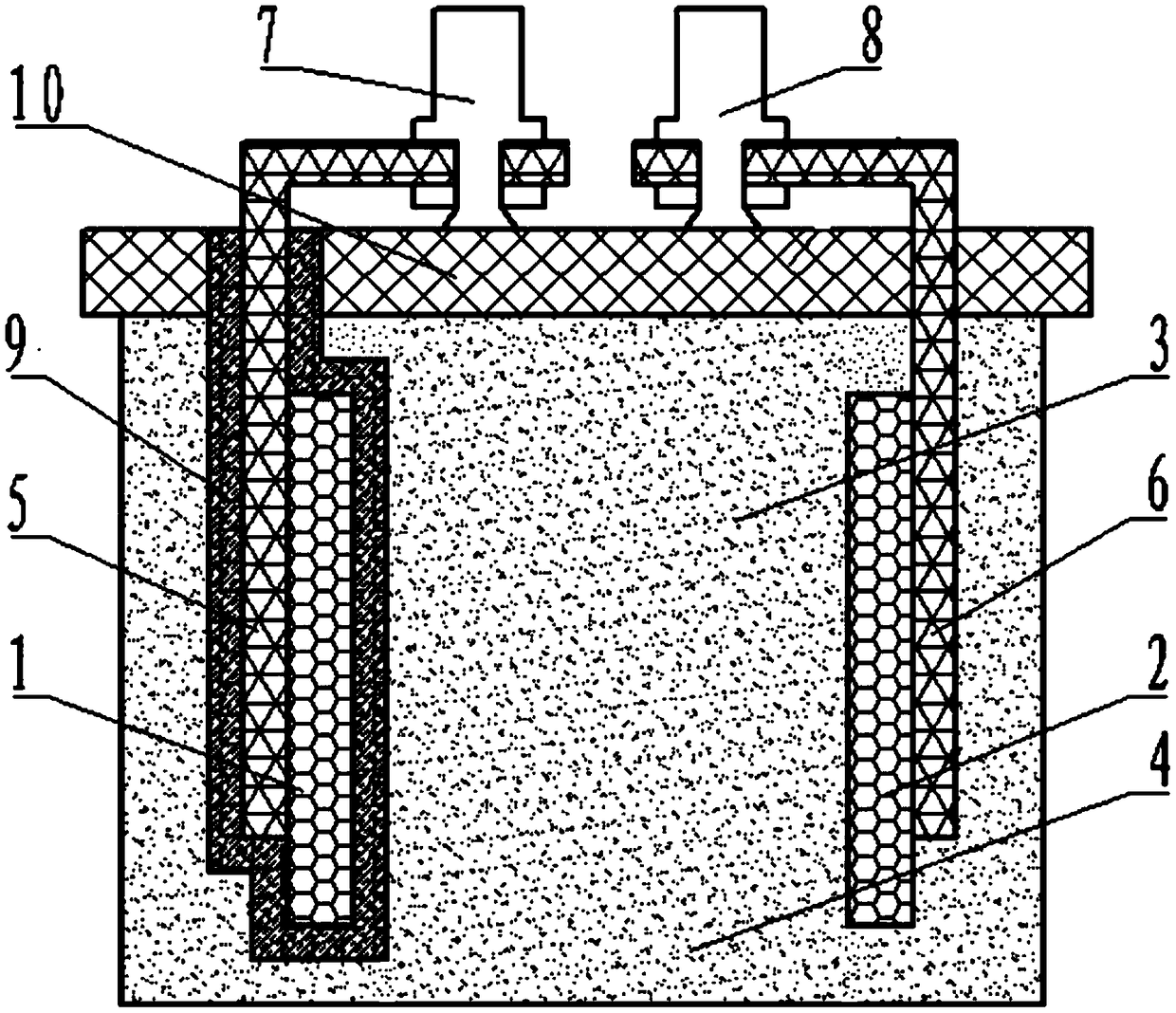
[0035] like figure 1 and figure 2 As shown, the embodiment provides a conductive polymer aluminum electrolytic capacitor led by a guide foil, including:

[0036] A capacitor core wound by an anode electrode foil 1, a cathode electrode foil 2, and a separator paper 3 arranged between the anode electrode foil 1 and the cathode electrode foil 2. The conductive polymer 4 is arranged on the anode electrode foil 1 and the cathode electrode foil 2, the conductive polymer 4 is filled with the surface of the cathode electrode foil 2, the surface of the anode electrode foil 1 and the surface of the separator paper 3;

[0037]The anode lead-out guide foil 5 is riveted on the anode electrode foil 1, and the cathode lead-out guide foil 6 is riveted on the cathode electrode foil 2; an isolation layer 10 is arranged above the isolation paper 3, and the isolation layer 10 is an insulating material, and the isolation layer 10 is A rubber plate formed by rubber potting, with a thickness of 5...

Embodiment 2

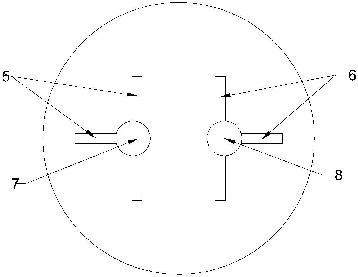
[0061] like figure 1 and image 3 As shown, the embodiment provides a conductive polymer aluminum electrolytic capacitor led by a guide foil, including:

[0062] A capacitor core wound by anode electrode foil 1, cathode electrode foil 2, and separator paper 3 arranged between the anode electrode foil 1 and cathode electrode foil 2. Conductive polymer 4 is arranged on the anode electrode foil 1, cathode electrode foil 2, the conductive polymer 4 is filled with the surface of the cathode electrode foil 2, the surface of the anode electrode foil 1 and the surface of the separator paper 3;

[0063] The anode lead-out guide foil 5 is riveted on the anode electrode foil 1, and the cathode lead-out guide foil 6 is riveted on the cathode electrode foil 2; an isolation layer 10 is arranged above the isolation paper 3, and the isolation layer 10 is an insulating material. Layer 10 is a rubber plate formed by rubber potting, with a thickness of 6mm. The positive lead-out terminal 7 and...

Embodiment 3

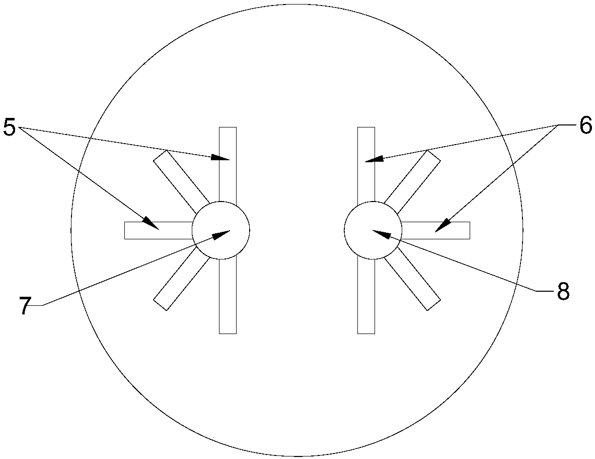
[0075] like figure 1 and figure 2 As shown, the embodiment provides a conductive polymer aluminum electrolytic capacitor led by a guide foil, including:

[0076] A capacitor core wound by anode electrode foil 1, cathode electrode foil 2, and separator paper 3 arranged between the anode electrode foil 1 and cathode electrode foil 2. Conductive polymer 4 is arranged on the anode electrode foil 1, cathode electrode foil 2, the conductive polymer 4 is filled with the surface of the cathode electrode foil 2, the surface of the anode electrode foil 1 and the surface of the separator paper 3;

[0077] The anode lead-out guide foil 5 is riveted on the anode electrode foil 1, and the cathode lead-out guide foil 6 is riveted on the cathode electrode foil 2; an isolation layer 10 is arranged above the isolation paper 3, and the isolation layer 10 is an insulating material. Layer 10 is a rubber plate formed by rubber potting, with a thickness of 10 mm. The positive lead-out terminal 7 ...


PUM

PropertyMeasurementUnit
thicknessaaaaaaaaaa
widthaaaaaaaaaa
lengthaaaaaaaaaa

Abstract

The invention discloses a lead foil lead-out conductive polymer aluminum electrolytic capacitor belonging to the technical field of capacitors. The lead foil lead-out conductive polymer aluminum electrolytic capacitor comprises an anode electrode foil, a cathode electrode foil, an isolation pap, a conductive polymer, an anode lead-out conductive foil, a cathode lead-out conductive foil, a positiveelectrode lead-out terminal, a negative electrode lead-out terminal, an oxide film and an isolation layer, wherein that conductive foil leads-out conductive polymer aluminum electrolytic capacitor comprise an anode electrode foil, a cathode electrode foil, a cathode lead-out conductive foil and an isolation layer. A method for manufacture a conductive polymer aluminum electrolytic capacitor withconductive foil extraction includes that step of impregnating and vacuum drying to form a continuous and stable electrolyte layer on the electrode foil, thereby improve the capacitance extraction rateof the capacitor. The electrolytic capacitor structure can be provided with multiple pairs of lead-out conductive foils on the single capacitor core, so that the capacitor can obtain lower ESR and higher capacitance lead-out rate; and the electrolytic capacitor structure can be provided with multiple pairs of lead-out conductive foils on the single capacitor core. At the same time, a novel manufacturing method is provided, which ensures that a large-size capacitor core can be fully filled with conductive polymer by drying at low temperature in vacuum, so as to obtain a continuous electrolytelayer and to overcome the difficulties of the prior art.

Description

technical field [0001] The invention relates to the technical field of capacitors, in particular to a conductive polymer aluminum electrolytic capacitor led out from a guide foil. Background technique [0002] Compared with ordinary aluminum electrolytic capacitors, conductive polymer aluminum electrolytic capacitors have the outstanding characteristics of low equivalent series resistance (ESR) at high frequencies, so they have the characteristics of large ripple current resistance, long life and high stability. With the continuous improvement of the power of electronic equipment, the requirement for the capacitance of a single capacitor of this type of capacitor is getting higher and higher, and people use various methods to increase the capacitance of a single capacitor. [0003] The core structure of the existing conductive polymer aluminum electrolytic capacitor generally adopts a lead-out structure, and is packaged with a rubber plug and an aluminum shell. In this stru...

Claims


Application Information

Patent Timeline
Patent Type & Authority Applications(China)
IPC IPC(8): H01G9/008H01G9/045
CPCH01G9/008H01G9/045Y02E60/13
Inventor 陈仙兵程学鹏程云来罗群锋
Owner 江西联晟电子股份有限公司
Why Eureka
Try Eureka