High withstand voltage flyback convert

A flyback converter, high withstand voltage technology, applied in the direction of instruments, DC power input conversion to DC power output, adjustment of electrical variables, etc., can solve problems such as failure to limit current, damage to resistor R1, product failure, etc., to achieve The effect of high reliability

Pending Publication Date: 2018-12-14
MORNSUN GUANGZHOU SCI & TECH
View PDF8 Cites 8 Cited by
  • Summary
  • Abstract
  • Description
  • Claims
  • Application Information

AI Technical Summary

Problems solved by technology

[0006] One, such as figure 2 As shown, when the switching tubes are turned on inconsistently, assuming that the switching tube Q1 is turned on first, the terminal voltage Vc1 of the capacitor C1 is greater than the terminal voltage Vc2 of the capacitor C2 at this time. Since the switching tube Q2 has not been turned on, at this time, the The polarity is upper positive and lower negative, the forward voltage V2 induced by the primary winding N2 will be greater than Vc2, and the forward voltage V2 will charge the capacitor C2 forward through the body diode of the switching tube Q2. A large negative voltage is generated on the current sampling resistor R0, which will affect the normal sampling of the control IC, resulting in poor consistency of the overcurrent point when the product is in batches
[0007] Two, such as image 3 As shown, when the switch tubes are turned off inconsistently, before the switch tubes Q1 and Q2 are turned off, the two primary windings N1 and N2 of the transformer both store energy, and the total stored energy is Assuming that the switch tube Q1 is turned off first at this time, since the switch tube Q2 is still in the conduction state, the secondary diode is still cut off. From the law of energy conservation, it can be known that the energy stored in the transformer remains unchanged, and the primary winding N1 is turned off because the switch tube Q1 is turned off. If there is no current, there is no energy. Therefore, all the stored energy of the transformer is added to the primary winding N2, which is by J 2 = J yields I 2 =2I, that is to say, when the switching tube Q1 is turned off first, the switching tube Q2 will bear twice the inductor current. There are reliability problems such as uneven heat generation of the switch tubes, frying machine and other reliability problems. Moreover, the products that actually use this circuit structure often have high input voltages, more than two stages in series, and more than two switch tubes in the circuit. The more, the more serious the problem and the lower the product reliability
[0009] However, for question two, if Image 6 As shown, when the switching tubes are turned off inconsistently, since the current of the inductor cannot change abruptly, the resistor R1 will not only fail to limit the current, but will generate a large power consumption on the resistor R1 as P= I 2 2 *R 1 , and after the product is ready, the sequence of turning off successively is fixed. After working for a long time, the resistor R1 will be damaged due to severe heating, which will eventually lead to product failure, and the more winding series series in the circuit structure, the more The more switch tubes connected in series, the more serious the problem and the lower the reliability of the product

Method used


Image

  • High withstand voltage flyback convert
  • High withstand voltage flyback convert
  • High withstand voltage flyback convert

Examples


no. 1 example

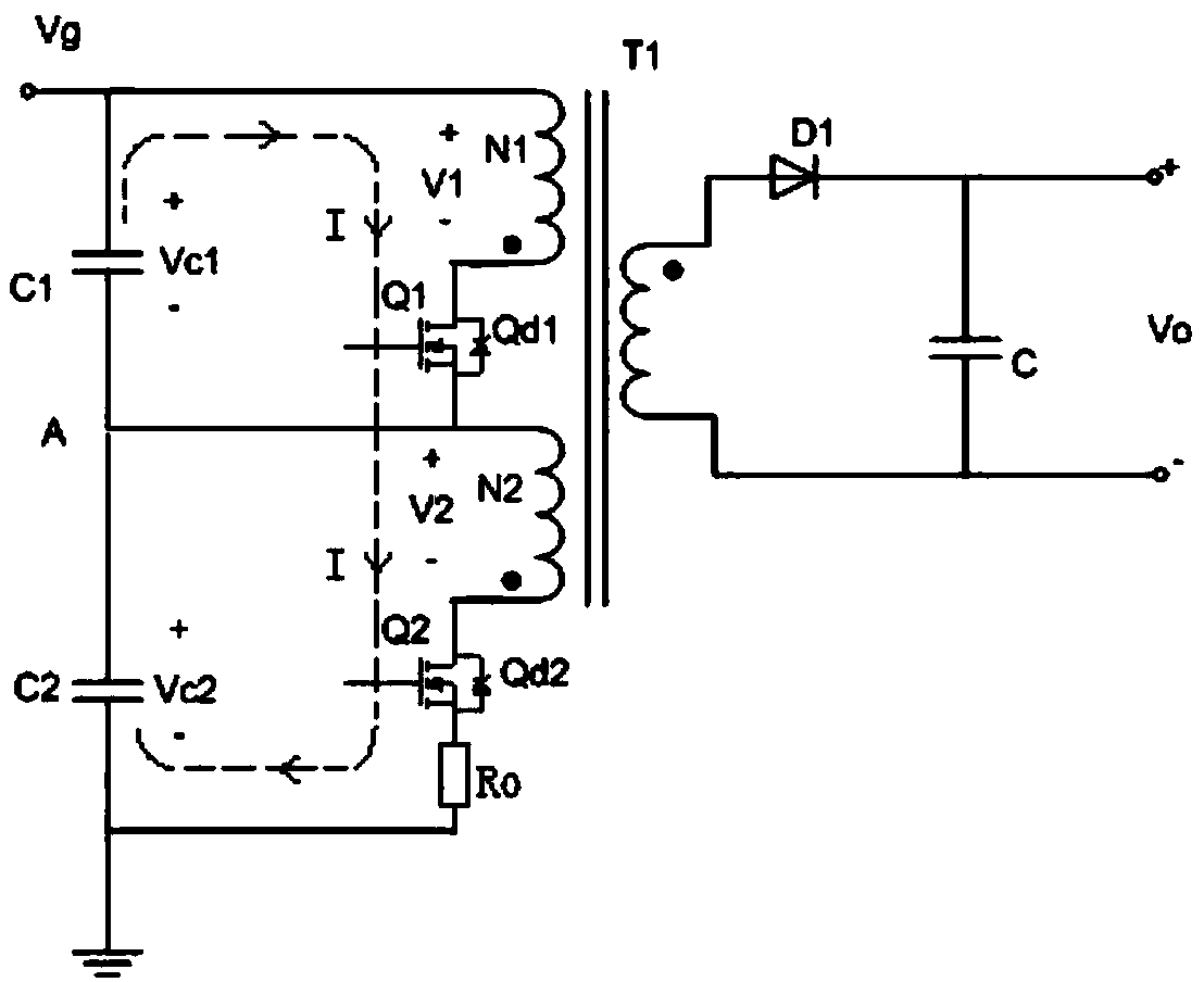
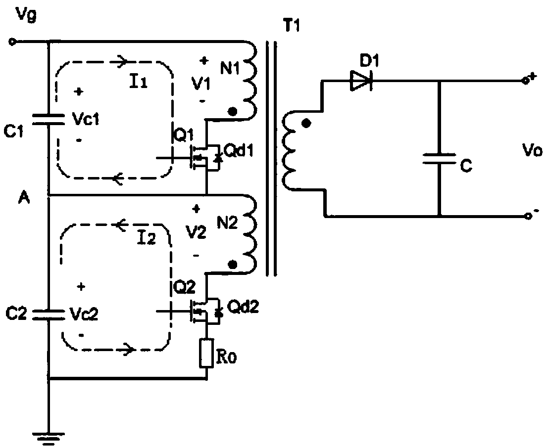
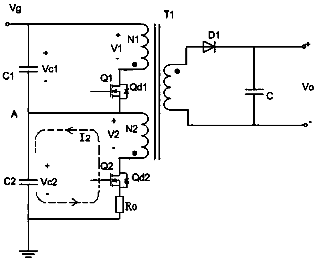
[0043] Such as Figure 7 Shown is the circuit schematic diagram of the high withstand voltage flyback converter of the first embodiment of the present invention, a high withstand voltage flyback converter, its circuit composition includes: an input circuit and an output circuit, and the input circuit includes two stages connected in series The primary winding unit and voltage equalizing unit of the same power converter, the primary winding unit of each stage is connected in parallel with the voltage equalizing unit, the primary winding units of each level are connected in series, and the voltage equalizing units of each level are connected in series; the first primary winding unit The input terminal of the DC voltage is connected to the positive voltage terminal, and the output terminal of the final primary winding unit is grounded.

[0044] The voltage equalizing unit is composed of capacitors. In this embodiment, the two stages of voltage equalizing units are capacitor C1 an...

no. 2 example

[0055] Such as Figure 10Shown is the circuit schematic diagram of the high withstand voltage flyback converter of the second embodiment of the present invention, and Figure 7 The difference is that this embodiment includes: N (N≥2) stages of the same power converter primary winding units and voltage equalizing capacitors, the working principle of the circuit after series superposition is the same as that of the first embodiment, and can achieve the same effect.


PUM


Abstract

A high withstand voltage flyback converter circuit provided by the invention includes at least two identical power converter primary winding units and voltage sharing capacitors, each stage of the primary winding unit is composed of the same primary winding, A switch transistor for controlling that on / off of the primary win and the same compensation circuit are formed, one end of the primary winding is used as the input end of the primary winding unit, the other end of the primary winding is used as the output end of the primary winding unit through the conductive inflow end of the switch tubeto the conductive outflow end of the switch tube, and the other end of the compensation circuit is used as the output end of the primary winding unit through the compensation circuit; The control terminal of each switch is provided with a synchronous driving signal, and the other end of each synchronous driving signal is connected to the output terminal of the primary winding unit, and all the primary windings are controlled in the same phase and share a magnetic core. Each primary winding unit is connected in series with each other, and each voltage equalizing capacitor is connected in series with each other. The series point of each primary winding unit is connected with the voltage-sharing series point of each voltage-sharing capacitor to form a corresponding loop.

Description

technical field [0001] The invention relates to a high withstand voltage converter circuit, in particular to an input series circuit of a DC-DC or DC-AC converter. Background technique [0002] In recent years, with the rapid development of power industries such as photovoltaic power generation and ultra-high voltage transmission, the input voltage of its power distribution system is very high, up to several thousand volts. It is difficult for existing conventional converters to have suitable high-voltage switching tubes to meet the design requirements. Requirements, in order to solve the problem of excessive voltage stress of the switch tube, the circuit structure of the converter input series can be adopted. [0003] figure 1 It is a well-known circuit structure of high withstand voltage overlapping flyback DC-DC converter with automatic voltage equalization function. The circuit structure was published in "High Voltage Overlapping Flyback DC -DC Converter Design". [0...

Claims


Application Information

Patent Timeline
Patent Type & Authority Applications(China)
IPC IPC(8): H02M3/335H02M1/32
CPCH02M1/32H02M3/3353
Inventor 申志鹏翁斌关文龙
Owner MORNSUN GUANGZHOU SCI & TECH
Why Eureka
Try Eureka