Eureka AIR delivers breakthrough ideas for toughest innovation challenges, trusted by R&D personnel around the world.

Novel electric heating pot and composite stamping process

An electric heating pan and a new type of technology can be applied to utensils with integral electric heating devices, special materials for cooking utensils, lids of cooking utensils, etc., and can solve the problems of power consumption, low heat transfer efficiency, and large environmental sanitation and pollution.

Pending Publication Date: 2018-12-18
ZHEJIANG TIANXI KITCHEN APPLIANCE CO LTD
View PDF10 Cites 2 Cited by
  • Summary
  • Abstract
  • Description
  • Claims
  • Application Information

AI Technical Summary

Problems solved by technology

The electric heating tube used in the existing electric heating pot is usually provided with a metal tube, and an electric heating wire is arranged in the metal tube, and it is filled with magnesium oxide powder. Since the metal tube is in point contact with the bottom of the pot body, the heat transfer efficiency is low and the heat energy is wasted. large phenomenon
In addition, the heating chamber of the current electric heating pot is heated by brazing heating elements for processing. If the fiber welding process reaches a temperature of 400~450 degrees, the composite bottom will be melted so that the heating tube is welded under the pot, which requires 30KW of electricity consumption. A large amount of electric energy, and a large amount of welding powder is required during fiber welding, and the environmental pollution is very serious, so it is necessary to improve

Method used


Image

  • Novel electric heating pot and composite stamping process
  • Novel electric heating pot and composite stamping process
  • Novel electric heating pot and composite stamping process

Examples


Embodiment Construction

[0023] The following descriptions are only preferred embodiments of the present invention, and do not limit the protection scope of the present invention. The present invention will be further described below in conjunction with the accompanying drawings and embodiments.

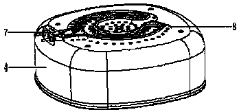
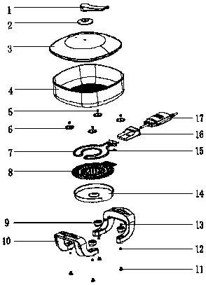
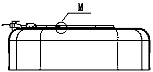
[0024] Embodiment, as shown in Fig. 1 to Fig. 6: a novel electric heating pot is characterized in that it comprises a pot cover, a pot body 4, a pot composite bottom, a power control device and a heat insulation device, wherein the pot composite bottom includes a heating device and Bottom cover; wherein the heating device includes a heating tube 7 and a composite negative 8; wherein the heating tube 7 is riveted to the bottom of the pot body 4 through the multiple negative 8; wherein the bottom cover is covered with a gap on the multiple negative 8; wherein the power control device is electrically connected At the side end of the heat pipe; wherein the power control device includes a power adjustment device 1...


PUM


Abstract

The invention discloses a novel electric heating pot. The novel electric heating pot comprises a pot cover, a pot body, a pot composite bottom, a power source control device and a heat insulation device; and the pot composite bottom comprises a heating pipe, a composite bottom sheet and a bottom cover. The composite bottom stamping process comprises that the heating pipe is placed between the bottom of the pot body and the composite bottom; the composite bottom sheet covers the heating tube to press the pot body through stamping; under the action of the external force, upsiding down edges around small holes of the composite bottom sheet are embedded in the bottom of the pot body, and the bottom of the pot body at a contact between the pot body and the small holes of the composite bottom sheet protrudes outward along the small holes; the protrusions are horizontally filled in the composite bottom sheet through secondary stamping, and the composite bottom sheet and the pot body are fastened together, so that the heating pipe is fixed on the pot body. The advantages of the novel electric heating pot are that the novel electric heating pot can be evenly heated in a short time and can save energy in use; and the process can save lots of electric energy in production, and can protect an environment.

Description

technical field [0001] The invention belongs to the technical field of cooking equipment, and in particular relates to a novel electric heating pan and a composite stamping process. Background technique [0002] Electric hot pot is a kind of pot that is widely used in people's daily life. The electric heating tube used in the existing electric heating pot is usually equipped with a metal tube, and the electric heating wire is arranged in the metal tube, and it is filled with magnesium oxide powder. Since the metal tube is in point contact with the bottom of the pot body, the heat transfer efficiency is low and the heat energy is wasted. large phenomenon. In addition, the heating chamber of the current electric heating pot is heated by brazing heating elements for processing. If the fiber welding process reaches a temperature of 400-450 degrees, the composite bottom will be melted so that the heating tube is welded under the pot, which requires 30KW of electricity consumptio...

Claims


Application Information

Patent Timeline
IPC IPC(8): A47J27/00A47J36/02A47J36/06A47J45/07B21D51/22
CPCA47J27/004A47J36/02A47J36/06A47J45/07B21D51/22
Inventor 不公告发明人
Owner ZHEJIANG TIANXI KITCHEN APPLIANCE CO LTD
Why Eureka
Eureka Blog
Learn More