Preparation method of MOFs polymer compound electrode and compound electrode and use method thereof

A composite electrode and polymer technology, applied in the field of electrodes, can solve problems such as poor compatibility and electrode surface shedding, and achieve the effects of simple production, increased adsorption rate, and improved catalytic oxidation efficiency

Inactive Publication Date: 2018-12-18
NANJING NORMAL UNIV CHANGZHOU INST OF INNOVATION & DEV
View PDF4 Cites 4 Cited by
  • Summary
  • Abstract
  • Description
  • Claims
  • Application Information

AI Technical Summary

Problems solved by technology

[0005] However, the structure of MOFs material itself is very stable, and the compatibility with direct compounding with titanium electrodes is very poor, and it is easy to fall off from the electrode surface during use.

Method used


Image

  • Preparation method of MOFs polymer compound electrode and compound electrode and use method thereof
  • Preparation method of MOFs polymer compound electrode and compound electrode and use method thereof
  • Preparation method of MOFs polymer compound electrode and compound electrode and use method thereof

Examples


Embodiment 1

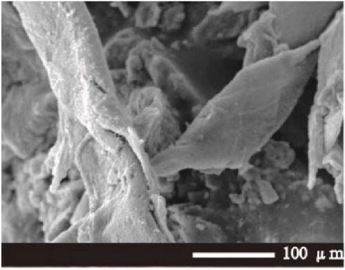
[0044] Take 0.1g of MIL-53(Al), 1g of PTFE, and 2g of carbon black in a 10mL volumetric flask, and pour it into a beaker after constant volume with DMF, stir at 140rpm for 15 minutes, take 0.3mL of the mixed solution and use a metal die to uniformly Cover it on a 4cm×1cm titanium electrode and dry it at 38°C. The section of the finished composite electrode material ( figure 2 ) and surface ( Figure 7 ) for scanning electron microscope test, and with the section of pure titanium electrode ( figure 1 ) and surface ( Figure 6 )comparing. Compared with the pure titanium electrode, the surface of the composite electrode material in Example 1 has an obvious MOFs crystal structure, and it can be seen that there is an additional modification layer in the cross section, which can confirm that the composite electrode material was successfully prepared.

Embodiment 2

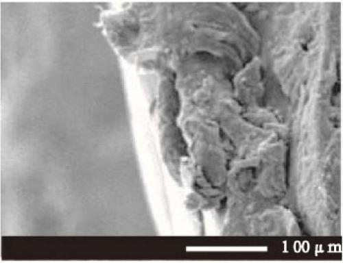
[0046] Take 0.3g of MIL-100(Fe), 1.5g of PVDF, and 1.5g of graphite in a 10mL volumetric flask, and pour it into a beaker after constant volume with acetonitrile, stir at 200rpm for 26 minutes, take 1.6mL of the mixed solution and use a metal die Cover evenly on a 4cm×4cm titanium electrode, and dry at 55°C. The section of the finished composite electrode material ( image 3 ) and surface ( Figure 8 ) for scanning electron microscope test, and with the section of pure titanium electrode ( figure 1 ) and surface ( Figure 6 )comparing. Compared with the pure titanium electrode, the surface of the composite electrode material in Example 2 has an obvious MOFs crystal structure, and it can be seen that there is an increased modification layer in the cross section, which can confirm that the composite electrode material was successfully prepared.

Embodiment 3

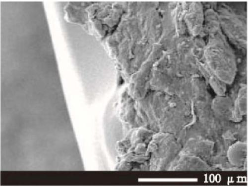
[0048] Take 0.4g of MIL-101(Cr), 0.5g of PE, and 0.5g of graphene in a 10mL volumetric flask, pour it into a beaker after constant volume with chloroform, stir at 240rpm for 48 minutes, and take 2.5mL of the mixed solution with metal The stamper is evenly covered on the 4cm×10cm titanium electrode, and dried at 66°C. The section of the finished composite electrode material ( Figure 4 ) and surface ( Figure 9 ) for scanning electron microscope test, and with the section of pure titanium electrode ( figure 1 ) and surface ( Figure 6 )comparing. Compared with the pure titanium electrode, the surface of the composite electrode material in Example 3 has obvious MOFs crystal structure, and it can be seen from the cross-section that there is an increased modification layer, which can confirm that the composite electrode material was successfully prepared.


PUM


Abstract

The invention belongs to the technical field of electrodes, and particularly relates to a preparation method of a MOFs polymer compound electrode material and the compound electrode material and a usemethod thereof. The preparation method of the compound electrode material is suitable for loading a MOFs polymer compound to an electrode surface by means of surface loading, and the catalytic oxidation performance of the compound electrode material is improved.

Description

technical field [0001] The invention relates to the technical field of electrodes, in particular to a method for preparing a MOFs polymer composite electrode material, a composite electrode material and a method for using the same. Background technique [0002] Electrocatalytic oxidation degradation of organic pollutants in water is an efficient and convenient method for wastewater treatment. In electrocatalytic oxidation, titanium electrode is a commonly chosen anode working electrode. Due to the stable size of the titanium electrode anode, the distance between the electrodes does not change during the electrolysis process, which can ensure that the electrolysis operation is carried out under the condition of stable cell voltage. At the same time, the working voltage of the titanium electrode is low, the power consumption is small, and the DC power consumption can be reduced by 10-20%. In addition, the titanium anode has a long working life and stronger corrosion resistan...

Claims


Application Information

Patent Timeline
Patent Type & Authority Applications(China)
IPC IPC(8): C02F1/461C02F1/72C02F101/30
CPCC02F1/46109C02F1/4672C02F1/725C02F2001/46142C02F2101/30C02F2201/4618
Inventor 杨朕杨维本胡宇翀李超蒋欣
Owner NANJING NORMAL UNIV CHANGZHOU INST OF INNOVATION & DEV
Why Eureka
Try Eureka