
Shear wall side forming staircase steel mold and mounting method

A shear wall and stair technology, which is applied in the fields of formwork/formwork/work frame, on-site preparation of building components, construction, etc., can solve problems such as rework, slag inclusion in stair construction joints, improper thickness of protective layer, etc. Safety and quality, lower construction cost, good fastening effect

Inactive Publication Date: 2018-12-18
CHINA MCC17 GRP
View PDF7 Cites 2 Cited by
  • Summary
  • Abstract
  • Description
  • Claims
  • Application Information

AI Technical Summary

Problems solved by technology

First of all, this practice usually leads to quality defects such as slag inclusions, sagging, cracks, and improper thickness of the protective layer in the construction joints of the stairs, which will have adverse effects on the safety of the stairs, the level of construction management, and social impact.
Inadequate treatment of the old and new concrete contact surfaces at construction joints will have a greater impact on the strength of the concrete contact surface and the integrity of the new and old concrete contact surfaces; inadequate control of the thickness of the protective layer will affect the durability of the stairs, and the sagging of the steps will affect the visual quality. It will bring trouble or even rework to the follow-up work, and cause manual chiseling and waste of materials; the presence of sand and gravel inclusions at the bottom will affect the integrity of the stairs
Furthermore, the traditional carpentry work, especially for the stair members on the side of the shear wall, leaves the stair construction joints on the stair sections, which has low labor efficiency and time-consuming, and is also very inconvenient for the superstructure shear wall formwork fabrication and installation. At the same time, this practice will easily lead to the occurrence of quality defects such as grout leakage and expansion at the hanging formwork of the stairs when the concrete of this layer of shear wall is poured.

Method used


Image

  • Shear wall side forming staircase steel mold and mounting method
  • Shear wall side forming staircase steel mold and mounting method

Examples


Embodiment 1

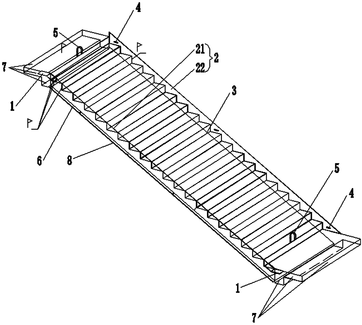
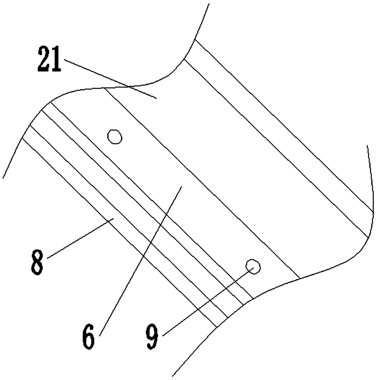
[0040] Such as Figure 1-2 Shown: .

[0041] A steel formwork for a shaped staircase on the side of a shear wall, comprising a shear wall, a concrete layer 7, and a support formwork 8 located between the concrete layers 7, the shear wall is reserved for lock-foot screws, and also includes a Stylized staircase steel formwork,

[0042] Stereotyped staircase steel mold:

[0043] Including a steel grating 1, which includes a top steel grating and a bottom steel grating,

[0044] Including a side panel 2, which includes a far wall side panel 21 and a near wall side panel 22,

[0045] including panel 3,

[0046] The upper opening of the side panel 21 of the far wall is flush with the upper opening of the panel 3, and the lower opening of the side panel 21 of the far wall closely fits with the reserved support template 8;

[0047] The lower opening of the side panel 22 near the wall is flush with the lower opening of the panel 3 , and the upper part of the side panel 22 close to...


PUM


Abstract

The invention discloses a shear wall side forming staircase steel mold and mounting method and belongs to the technical field of construction technology. The steel mold includes a shear wall, concretelayers and the support formworks positioned between the concrete layers, and further comprises a steel grid plate comprising a top steel grid plate and a bottom steel grid plate. The steel mold includes a side panel comprising a distal wall side panel and a near wall side panel. The steel mold includes a panel, wherein an upper opening of the distal wall side panel is flush with an upper openingof the panel, and a lower opening of the distal wall side panel fits closely a remaining support formwork. The lower opening of the distal wall side panel is flush with the lower opening of the panel,and an upper portion of the distal wall side panel fits closely the shear wall. The invention changes an existing traditional woodworking method of mounting a shear wall side staircase formwork by using formworks and adopts the more convenient forming staircase steel mold method. Construction joints of a staircase section are left on the upper and lower rest platforms, common quality defects of astaircase of a cast-in-place structure are avoided, and safety and quality of the shear wall side staircase and the shear wall are ensured.

Description

technical field [0001] The invention belongs to the technical field of building construction, and in particular relates to a steel mold for a stereotyped staircase on the side of a shear wall and an installation method. Background technique [0002] At present, with the continuous improvement of material living standards, people's requirements for housing, infrastructure and other architectural patterns are also constantly increasing, and architectural design styles are also constantly developing, and the design patterns of high-rise and super high-rise buildings are increasing. At present, the structural form of high-rise and super high-rise buildings usually adopts the core tube reinforced concrete structure. According to the relevant specifications, the construction joints of the stairs must be left within 1 / 3 of the end of the stair slab. First of all, this practice usually leads to quality defects such as slag inclusions, sagging, cracks, and improper thickness of the ...

Claims


Application Information

Patent Timeline
IPC IPC(8): E04G13/06E04G21/14
CPCE04G13/062E04G21/14
Inventor 刘忠正
Owner CHINA MCC17 GRP
Learn More