Self-driven heat pipe circulation heat exchanger

A heat pipe circulation and self-driving technology, applied in indirect heat exchangers, lighting and heating equipment, etc., can solve the problems of difficult normal operation of gravity circulation heat pipes, inability to achieve continuous operation, complex structure, etc., to avoid power plant control problems, The effect of expanding the scope of circulation application and occupying a small space

Inactive Publication Date: 2018-12-18
NANJING UNIV OF AERONAUTICS & ASTRONAUTICS +1
View PDF8 Cites 2 Cited by
  • Summary
  • Abstract
  • Description
  • Claims
  • Application Information

AI Technical Summary

Problems solved by technology

[0003] The gravity cycle heat pipe relies on gravity to return liquid, so the condenser must be higher than the evaporator to work normally, but in many practical applications, the above conditions cannot be met, which greatly limits the application of the gravity cycle heat pipe
Especially in the field of aerospace, gravity circulation heat pipes are difficult to operate normally in the case of no gravity or even antigravity
[0004] The heat pipe cycle driven by a mechanical pump can solve the problem of liquid return in the heat pipe cycle in no-height difference and zero-gravity scenarios, but it needs an external power drive, and the addition of a mechanical pump destroys the self-adaptive performance of the heat pipe cycle, which brings many difficulties to the operation and control of the system
The separated heat pipe heat exchanger, which is self-driven by the pressure difference of the working fluid, needs multiple valves to switch and control the pressure difference to operate intermittently. The structure is complex and continuous operation cannot be achieved.
[0005] In summary, there is a lack of a heat pipe circulation heat exchanger in the prior art, which can automatically drive the working fluid between the condenser and the evaporator for continuous circulation.

Method used


Image

  • Self-driven heat pipe circulation heat exchanger
  • Self-driven heat pipe circulation heat exchanger
  • Self-driven heat pipe circulation heat exchanger

Examples


Embodiment Construction

[0027] In order to enable those skilled in the art to better understand the technical solutions of the present invention, the present invention will be further described in detail below in conjunction with specific embodiments.

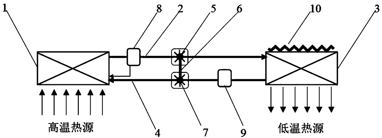
[0028] Embodiments of the present invention provide a self-driven heat pipe circulation heat exchanger, such as figure 1 shown, including:

[0029] Evaporator 1, gas pipe 2, condenser 3, liquid pipe 4, driving wheel 5, rotating shaft 6, driven wheel 7.

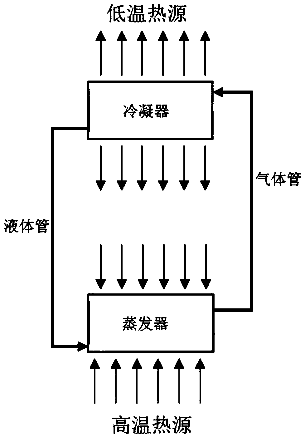
[0030] The evaporator 1 is connected to the condenser 3 through a gas pipe 2 and a liquid pipe 4 to form a closed space that can circulate, and the closed space is filled with a phase change working medium.

[0031] An electric heating band 10 is arranged on the condenser 3 . Before starting, the working medium is in the condenser 3. In order to start smoothly, start the electric heating belt 10 to heat the working medium in the condenser 3, so that the working medium is in the evaporator 1 before s...


PUM


Abstract

The invention discloses a self-driven heat pipe circulation heat exchanger, and relates to the field of heat energy transmission. The gravity cycle can be broken through, and working medium between acondenser and an evaporator can be automatically driven to circulate. The self-driven heat pipe circulation heat exchanger comprises the evaporator, a gas pipe, the condenser, a liquid pipe, a drivingwheel, a rotating shaft and a driven wheel. During the circulation working process of the heat pipe, gas-state working medium in the gas pipe drives the driving wheel to rotate, the driving wheel drives the driven wheel to rotate through the rotating shaft, and the driven wheel drives liquid working medium in the liquid pipe to return to the evaporator. The volume flow of the gas-state working medium in the gas pipe is much larger than the volume flow of the liquid working medium in the liquid pipe, coaxial rotation and the like, the pressure head obtained by the liquid working medium is farlarger than the lost pressure head of the gas working medium, and the pressure head can overcome the flowing resistance in the whole flowing process. A small amount of heat transfer temperature difference is sacrificed to generate mechanical energy, so that liquid working medium backflow is promoted, the gravity constraint is avoided, the circulating running range of the heat pipe is expanded, external driving is not needed, and the self-adaptive performance is achieved.

Description

technical field [0001] The invention relates to the field of heat energy transmission, in particular to a self-driven heat pipe circulation heat exchanger. Background technique [0002] Gravity cycle heat pipe, also known as split heat pipe heat exchanger, is a high-efficiency heat transfer device that relies on phase change heat transfer and gravity return liquid. A typical gravity cycle heat pipe includes an evaporator, gas tube, condenser, and liquid tube. When working, the phase-change working medium is heated and evaporated in the evaporator, and the gaseous working medium produced flows into the condenser through the gas tube, and condenses into a liquid working medium in the condenser, and the liquid working medium flows back into the evaporator under the action of gravity , to complete the phase change heat transfer cycle. Gravity cycle heat pipe heat exchangers are widely used in the fields of industrial waste heat recovery, solar energy utilization, aerospace, an...

Claims


Application Information

Patent Timeline
Patent Type & Authority Applications(China)
IPC IPC(8): F28D15/02
CPCF28D15/0266F28D2015/0291
Inventor 张朋磊张大林沈浩陈维建杨晓睿
Owner NANJING UNIV OF AERONAUTICS & ASTRONAUTICS
Why Eureka
Try Eureka