Transmitted Wavefront Detection Interferometer

A wavefront detection and transmitted wave technology, applied in the field of interferometry, can solve the problems of inability to measure wavefront tilt information, complex data processing steps, and increase system costs, achieving a simple structure, increasing the available wavelength range, and reducing system costs. Effect

Active Publication Date: 2020-10-16
SHANGHAI INST OF OPTICS & FINE MECHANICS CHINESE ACAD OF SCI
View PDF5 Cites 0 Cited by
  • Summary
  • Abstract
  • Description
  • Claims
  • Application Information

AI Technical Summary

Problems solved by technology

However, the data processing steps of this system are complicated, and the wavefront tilt information of the transmitted wavefront cannot be measured.
[0005] The above-mentioned prior technologies all use free-space optical paths, and the experimental debugging is complicated and costly; in addition, when the above-mentioned technologies use light sources with multiple wavelengths for simultaneous detection, they all need achromatic optical elements, which increases the system cost; while multi-wavelength detection can use To expand the dynamic range of the system measurement, various physical parameters can also be calculated according to the transmitted wavefronts of different wavelengths

Method used


Image

  • Transmitted Wavefront Detection Interferometer
  • Transmitted Wavefront Detection Interferometer
  • Transmitted Wavefront Detection Interferometer

Examples


Embodiment Construction

[0035] The present invention will be further described below in conjunction with the accompanying drawings and embodiments, but the embodiments do not limit the protection scope of the present invention.

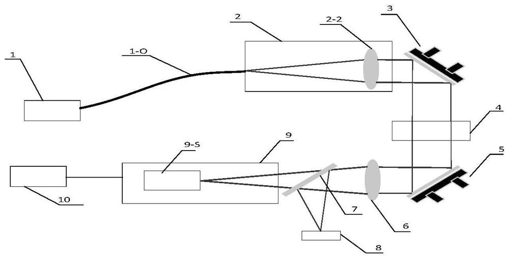
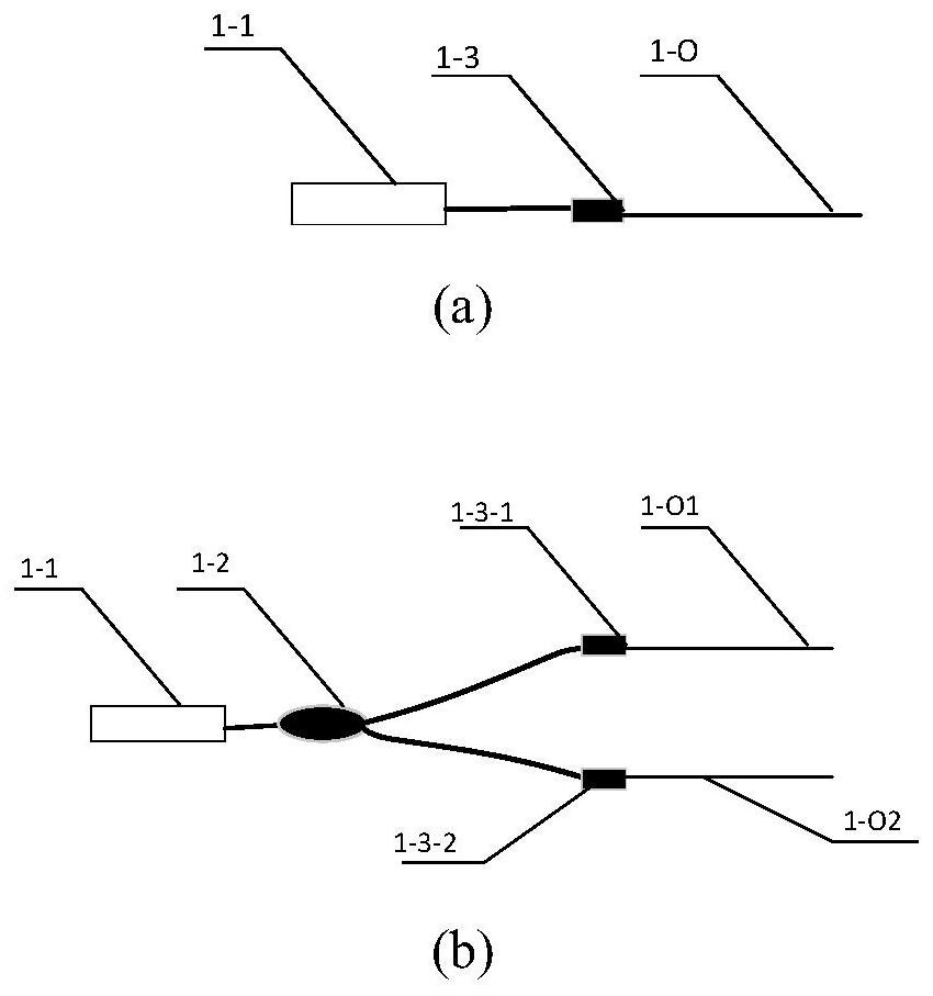
[0036] figure 1 It is a structural schematic diagram of the first embodiment of the transmitted wavefront detection interferometer of the present invention; its composition includes: a light source unit 1, a transmission fiber 1-0, a collimation unit 2, a first turning mirror 3, a measured medium 4, a second Turning mirror 5, converging mirror 6, wavefront detection unit 9, control unit 10;

[0037]The position and connection relationship of the above components are: the output light of the light source unit 1 enters the collimation unit 2 through the transmission fiber 1-0, and the collimation unit 2 collimates the input light into parallel light output; the output light of the collimation unit 2 passes through the first After a turning mirror 3 adjusts the transmission di...


PUM


Abstract

The invention relates to a transmission wavefront detection interferometer, which comprises a light source unit, a transmission optical fiber, a collimating unit, a first transition mirror, a measuredmedium, a second transition mirror, a convergence mirror, a wavefront detection unit and a control unit. The interferometer carries out optical path layout by using an optical fiber and has the advantages of simple structure, easy assembly, strong anti-interference, adjustable signal strength, etc. Moreover, when the system is subjected to dual-wavelength measurement expansion, a collimating unittwo-tone spectroscope and an interferometer unit two-tone spectroscope are used so that a low-cost dual-wavelength transmission wavefront detection system can be established conveniently.

Description

technical field [0001] The invention relates to the field of interferometric measurement, in particular to a transmitted wavefront detection interferometer. Background technique [0002] The transmitted wavefront is an important parameter for evaluating optical media. For example, the transmitted wavefront of the imaging system reflects the imaging quality of the imaging system; the transmitted wavefront of the flow field can reflect the density distribution and temperature distribution of the flow field. [0003] The free-space optical path Mach-Zehnder interferometer is a common system for measuring the transmitted wavefront (see prior art 1: Chen Zhimin, Wang Hailong, Yin Muliang, Application of laser double-exposure holographic interferometry in measuring jet density field, application of laser, 2007,27(3):201-204.), but the optical path structure of this system is complicated, the system cost is high, the installation and adjustment are difficult during use, and the op...

Claims


Application Information

Patent Timeline
Patent Type & Authority Patents(China)
IPC IPC(8): G01B9/02
CPCG01B9/02015
Inventor 唐锋王向朝徐静浩卢云君郭福东
Owner SHANGHAI INST OF OPTICS & FINE MECHANICS CHINESE ACAD OF SCI
Why Eureka
Try Eureka