Eureka AIR delivers breakthrough ideas for toughest innovation challenges, trusted by R&D personnel around the world.

Scintillator-plate fluorescent-fiber composite sensor

A composite sensor and fluorescent optical fiber technology, which is applied in the direction of instruments, scientific instruments, measuring devices, etc., can solve the problems of increased difficulty in diagnosis, and achieve the effects of avoiding high transmission loss, increasing accuracy and sensitivity, and high anti-interference ability

Inactive Publication Date: 2018-12-18
STATE GRID GASU ELECTRIC POWER RES INST
View PDF0 Cites 3 Cited by
  • Summary
  • Abstract
  • Description
  • Claims
  • Application Information

AI Technical Summary

Problems solved by technology

However, in actual use, optical signals and UHF signals need to be analyzed at the same time, which increases the difficulty of later fault diagnosis

Method used


Image

  • Scintillator-plate fluorescent-fiber composite sensor
  • Scintillator-plate fluorescent-fiber composite sensor
  • Scintillator-plate fluorescent-fiber composite sensor

Examples


Embodiment 1

[0024] Now in conjunction with embodiment, accompanying drawing, the present invention will be further described:

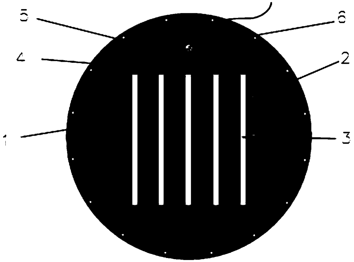
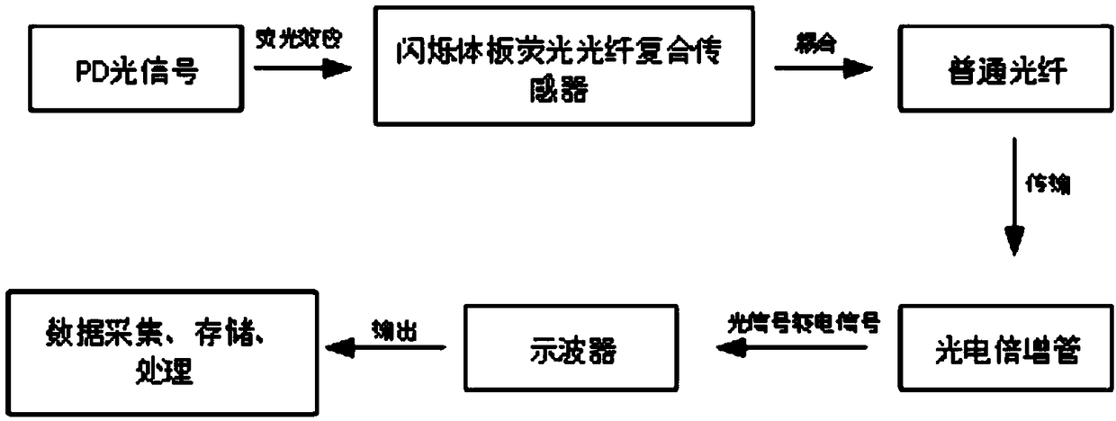
[0025] figure 1 It is a top view of the structure of this embodiment. As shown in the figure, a scintillator plate fluorescent fiber composite sensor includes: GIS cover plate 1, fluorescent scintillator plate 2, fluorescent optical fiber 3, optical coupler 4, and ordinary optical fiber 5.

[0026] The scintillator plate 2 is a fluorescent scintillator plate doped with rare earth elements that are very sensitive to weak light, and it is installed on the inner surface of the GIS cover plate 1, that is, close to the SF6 gas side. The fluorescent scintillator plate 2 is closely attached to the GIS cover plate 1 Together, no gaps. The contact surface between the cover plate and the scintillator plate is also optionally covered with transparent acrylate polymer glue for fixing the scintillator plate.

[0027] The fluorescent optical fibers 3 are evenly distributed ...


PUM


Abstract

The invention relates to the field of partial discharge detection of gas insulated switchgear (GIS), particular to a scintillator-plate fluorescent-fiber composite sensor. The sensor comprises a GIS cover plate, a fluorescent scintillator plate, a fluorescent fiber, a fiber coupler, and a conventional fiber. The fluorescent fiber receives optical signals generated by partial discharge and enhancesoutput signals with the fluorescent scintillator plate; and the fiber coupler and the conventional fiber transmit the optical signals to a signal receiving end. The beneficial effect of the inventionis that the fluorescent scintillator plate is used to enhance the fluorescent fiber and constitute the composite-structure fiber sensor, which is installed on the GIS cover plate to measure partial discharge signals. The sensor has the advantages of strong anti-jamming ability, strong output signals, and low transmission loss.

Description

technical field [0001] The invention relates to the field of partial discharge detection of gas-insulated combined electrical appliances (GIS), in particular to a scintillator plate fluorescent optical fiber composite sensor. Background technique [0002] Compared with open transmission equipment, gas insulated combined electrical equipment (GIS) has the advantages of small footprint, less external interference, safe and stable operation, good for environmental protection, long maintenance cycle, and small maintenance workload. In recent years, it has gradually replaced the traditional Open substation. However, in the process of manufacturing and transportation of GIS equipment, there will inevitably be insulation defects. Under conditions such as high voltage and overheating, partial discharges will occur at these insulation defects, which will cause the decomposition of sulfur hexafluoride and cause insulation degradation. If the power is not cut off and repaired in time...

Claims


Application Information

Patent Timeline
IPC IPC(8): G01T1/20
CPCG01T1/201
Inventor 张广东杨军亭温定均陈宏刚马振祺王津张家午孙涛杨佩佩张晓星尹佳张引
Owner STATE GRID GASU ELECTRIC POWER RES INST
Why Eureka
Eureka Blog
Learn More