
A monitoring system and method used in medical equipment

A technology of medical equipment and monitoring system, applied in the medical field, can solve the problems of MRI equipment not operating normally, occupying a large aperture space, and inconvenient for patient monitoring, etc., so as to improve the quality of monitoring imaging, save space, and improve convenience.

Active Publication Date: 2020-12-22
SHANGHAI UNITED IMAGING HEALTHCARE
View PDF11 Cites 0 Cited by
  • Summary
  • Abstract
  • Description
  • Claims
  • Application Information

AI Technical Summary

Problems solved by technology

However, due to the large number of cables of the camera equipment, it is easy to be entangled, the installation is complicated, and the aperture space is large, so it is not convenient to monitor the patient
And for nuclear magnetic resonance equipment with high electromagnetic compatibility requirements, since the camera in the imaging equipment will generate electrical signals during operation, it will generate certain electromagnetic interference to the nuclear magnetic resonance equipment, resulting in the failure of the nuclear magnetic resonance equipment to operate normally.
Moreover, the existing cameras all have metal shells, so that artifacts often exist in the images collected by the camera, which greatly reduces the imaging quality.

Method used


Image

  • A monitoring system and method used in medical equipment
  • A monitoring system and method used in medical equipment
  • A monitoring system and method used in medical equipment

Examples


Embodiment 1

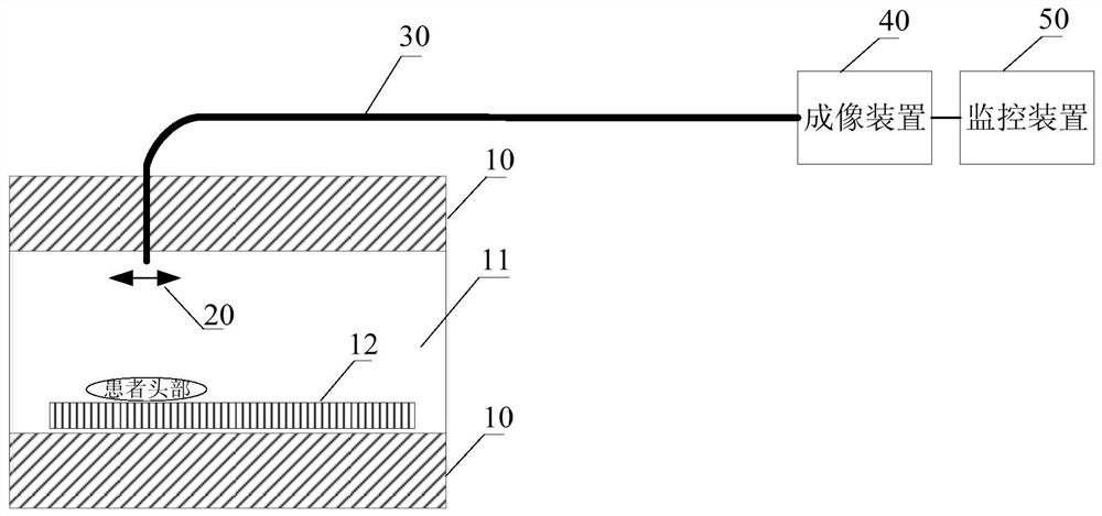
[0023] figure 1 It is a schematic structural diagram of a monitoring system used in medical equipment provided by Embodiment 1 of the present invention. This embodiment is applicable to real-time monitoring of patients within the aperture of the medical equipment. In this embodiment, the medical equipment includes but It is not limited to magnetic resonance equipment MR, computerized tomography equipment CT, PET / CT (Positron Emission Tomography, positron emission tomography), PET / MR and other equipment. like figure 1 As shown, the medical device 10 includes an aperture 11 for access to a scanning couch 12. The monitoring system includes:

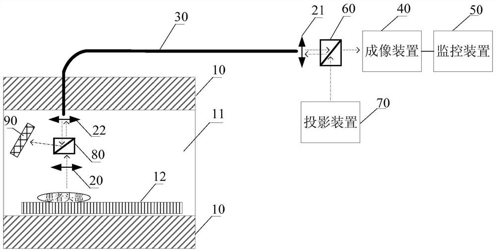
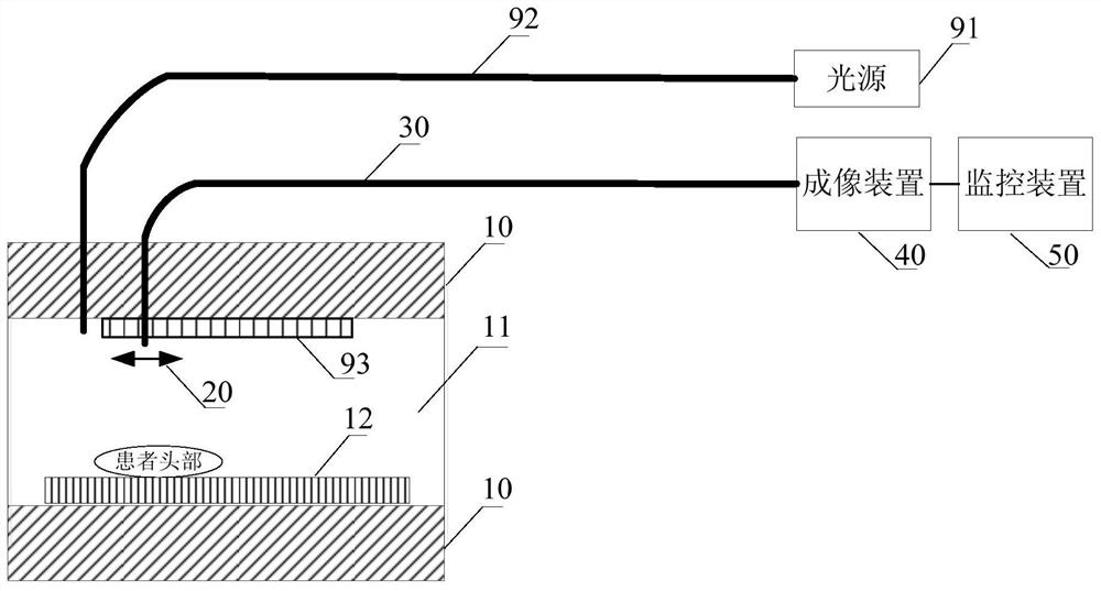
[0024] The acquisition device 20 is arranged on the inner wall of the aperture 11 or on the scanning bed 12, and is used to collect the first optical signal corresponding to the monitoring area; the optical fiber transmission bundle 30, the first end of the optical fiber transmission bundle 30 is connected with the acquisition device 20, an...

Embodiment 2

[0051] Figure 4 It is a flow chart of a monitoring method used in medical equipment provided by Embodiment 2 of the present invention. This embodiment is applicable to the situation of real-time monitoring of patients within the aperture of the medical equipment. This method can be executed by the monitoring system provided in the first embodiment. In this embodiment, the medical equipment includes but not limited to magnetic resonance equipment MR, computerized tomography equipment CT, PET / CT, PET / MR and other equipment. like Figure 4 As shown, the method specifically includes the following steps:

[0052] S110. Collect the first optical signal corresponding to the monitoring area of ​​the medical equipment through the collection device.

[0053] Wherein, the collecting device refers to a device for collecting optical signals. Exemplarily, the acquisition device may be a lens or a lens group, wherein the lens may be composed of one or more lenses, and the lenses may be ...


PUM


Abstract

The embodiment of the invention discloses a monitoring system and method used in medical equipment. The system includes: a collection device, which is arranged on the inner wall of the aperture or on the scanning bed, and is used to collect the first optical signal corresponding to the monitoring area; an optical fiber transmission bundle, the first end of which is connected to the collection device, and is used to transmit the first optical signal The signal is transmitted from the first end of the optical fiber transmission bundle to the second end of the optical fiber transmission bundle; the imaging device is connected with the second end of the optical fiber transmission bundle, and is used to receive the first optical signal transmitted by the second end of the optical fiber transmission bundle, and converting the first optical signal into a first electrical signal; a monitoring device connected to the imaging device for generating a monitoring image according to the first electrical signal, and displaying the monitoring image on a display interface of the monitoring device. The technical solutions of the embodiments of the present invention can simplify the existing imaging equipment, save occupied space, and thus improve the convenience of patient monitoring.

Description

technical field [0001] The embodiments of the present invention relate to the medical field, and in particular to a monitoring system and method used in medical equipment. Background technique [0002] In the medical field, it is often necessary to use medical equipment to perform preliminary diagnosis and scans on patients, so that doctors can better understand the patient's condition and formulate the best treatment plan. Generally, a medical device with a scanning aperture can be used to diagnose a patient, such as a nuclear magnetic resonance device (Magnetic Resonance, MR for short), an electronic computer tomography device (Computed Tomography, CT for short), and the like. Wherein, the nuclear magnetic resonance equipment is a medical diagnostic equipment for scanning and imaging the patient or other objects in the MR aperture based on the detected radio frequency signal from the precessing nuclear magnetic moment. [0003] When using medical equipment to scan a patie...

Claims


Application Information

Patent Timeline
Patent Type & Authority Patents(China)
IPC IPC(8): H04N7/18H04N7/22
CPCH04N7/18H04N7/22A61B5/0064A61B5/055A61B6/032G01R33/281
Inventor 张峰
Owner SHANGHAI UNITED IMAGING HEALTHCARE
Learn More