Smoke cooling, condensing, dehumidifying, pollution removing, reheating and white eliminating system and method

A flue gas condensation and flue gas cooling technology, applied in separation methods, chemical instruments and methods, dispersed particle separation, etc., can solve the problems of high construction and operation costs of whitening systems

Pending Publication Date: 2018-12-21
XI AN JIAOTONG UNIV
View PDF20 Cites 24 Cited by
  • Summary
  • Abstract
  • Description
  • Claims
  • Application Information

AI Technical Summary

Problems solved by technology

[0006] In order to reduce the price and operating cost of the flue gas condensation, dehumidification, decontamination, decontamination, heating and whitening device, and promote the development of flue gas condensation and whitening technology, the purpose of the present invention is to provide a flue gas cooling, condensation, dehumidification, decontamination, decontamination, reheating and whitening system and method , the invention solves the problem of high construction and operating costs of the whitening system, introduces multiple cold sources, recycles and utilizes the waste heat of the flue gas in steps, removes pollutants and recycles water resources while eliminating white smoke, and promotes condensation, dehumidification and whitening of flue gas The development of technology to contribute to the mitigation and elimination of smog

Method used


Image

  • Smoke cooling, condensing, dehumidifying, pollution removing, reheating and white eliminating system and method
  • Smoke cooling, condensing, dehumidifying, pollution removing, reheating and white eliminating system and method
  • Smoke cooling, condensing, dehumidifying, pollution removing, reheating and white eliminating system and method

Examples


Embodiment Construction

[0039] The invention will be described in detail below in conjunction with the accompanying drawings and specific embodiments.

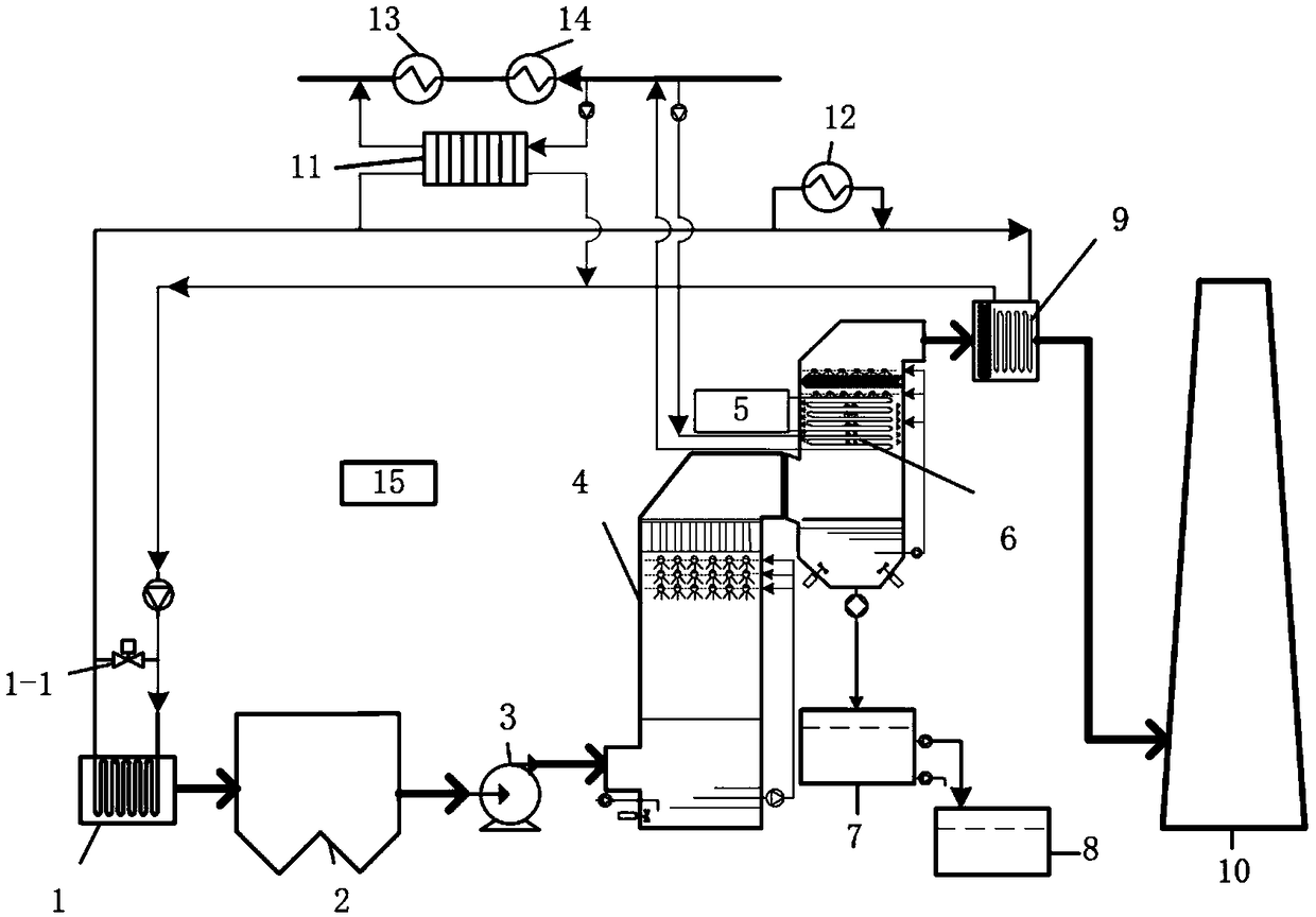
[0040] Such as figure 1 As shown, a flue gas cooling, condensation, dehumidification, decontamination, decontamination, reheating and whitening system of the present invention includes a flue gas deep cooler 1, an electrostatic precipitator 2, an induced draft fan 3, a desulfurization tower 4, a cold source 5, and flue gas condensation heat exchange 6, sedimentation tank 7, desulfurization process water tank 8, flue gas reheater 9, chimney 10, condensate heater 11, auxiliary heat heater 12, No. ;The exhaust gas from the boiler body first enters the flue gas deep cooler 1, recovers the waste heat of the flue gas at 150°C to 90°C in the flue gas, and uses it to heat the main condensate 5-1 and reheat the flue gas; the flue gas then enters the electrostatic precipitator in turn 2, induced draft fan 3, desulfurization tower 4; the wet saturated flue gas...


PUM


Abstract

The invention discloses a smoke cooling, condensing, dehumidifying, pollution removing, reheating and white eliminating system and method. The system comprises a smoke deep cooler, a smoke condensingand heat exchanging device, a smoke reheater, a cold source and the like; the smoke deep cooling process is carried out to supply a heat source for reheating smoke, so as to heat main condensing waterand decrease the smoke temperature at an outlet of a desulfurizing tower; the main condensing water can be heated in the smoke condensing process, the heat source is supplied to a heat pump, the water resource is recovered, and the water content of smoke is decreased; the relative humidity of exhausted smoke is reduced in the smoke reheating process, so that white smoke can be visibly removed. The invention further discloses a cooling, condensing, dehumidifying, pollution removing, reheating and white eliminating method. According to the system and the method, the structure of a condensing and heat exchanging device is innovated; 316L is adopted to replace fluoroplastic, titanium alloy and the like; a mechanical ventilating brine tower and an intelligent adjusting and controlling system are launched, so that the construction cost and the energy consumption of the device and a system can be decreased; the afterheat in the smoke can be recovered by steps while the white smoke is visiblyremoved; 50% or more than 50% of PM2.5, SO3 and 15% or more than 15% of NOx can be removed; and the environment protection benefit and the economic benefit are ensured.

Description

technical field [0001] The invention relates to the field of flue gas condensation, dehumidification, decontamination, heating and whitening elimination, in particular to a kind of fossil fuel, biomass fuel, flue gas after garbage incineration and wet flue gas after wet desulfurization, deep removal of pollutants and reheating to eliminate whitening Smoke systems and methods. Background technique [0002] my country's economy continues to develop at a high speed, the consumption of fossil energy is increasing year by year, the air quality is deteriorating day by day, and smog occurs frequently all over the country. In order to control the emission of air pollutants, the thermal power industry has proposed ultra-low emission standards, requiring SO 2 <20mg / m 3 . In order to achieve ultra-low emission standards, most thermal power plants use limestone / gypsum wet desulfurization to remove SO 2 . SO emissions can be reduced by wet desulfurization 2 The concentration is ...

Claims


Application Information

Patent Timeline
Patent Type & Authority Applications(China)
IPC IPC(8): B01D53/26
CPCB01D53/26B01D53/265
Inventor 赵钦新邓世丰王云刚梁志远
Owner XI AN JIAOTONG UNIV
Why Eureka
Try Eureka