Energy-saving and environment-friendly fuel gas burner

An energy-saving and environmental-friendly, gas-fired burner technology, which is applied to gas-fuel burners, burners, combustion methods, etc., can solve the problem that the burner cannot be fixed, the air volume of the air supply system cannot be flexibly adjusted, and the environmental protection and energy-saving of the gas burner cannot be realized. and other problems to achieve the effect of saving gas and avoiding waste

Inactive Publication Date: 2018-12-21
DIMENSION TECH
View PDF12 Cites 2 Cited by
  • Summary
  • Abstract
  • Description
  • Claims
  • Application Information

AI Technical Summary

Problems solved by technology

[0004] Aiming at the deficiencies in the prior art, the purpose of the present invention is to provide an energy-saving and environment-friendly gas burner, so as to solve the problem that in the above-mentioned background technology, the environment-friendly and energy-saving of the gas burner cannot be realized, the burner cannot be stably fixed, and the delivery rate cannot be flexibly adjusted. The problem of the size of the air volume in the wind system

Method used


Image

  • Energy-saving and environment-friendly fuel gas burner
  • Energy-saving and environment-friendly fuel gas burner
  • Energy-saving and environment-friendly fuel gas burner

Examples


Embodiment 1

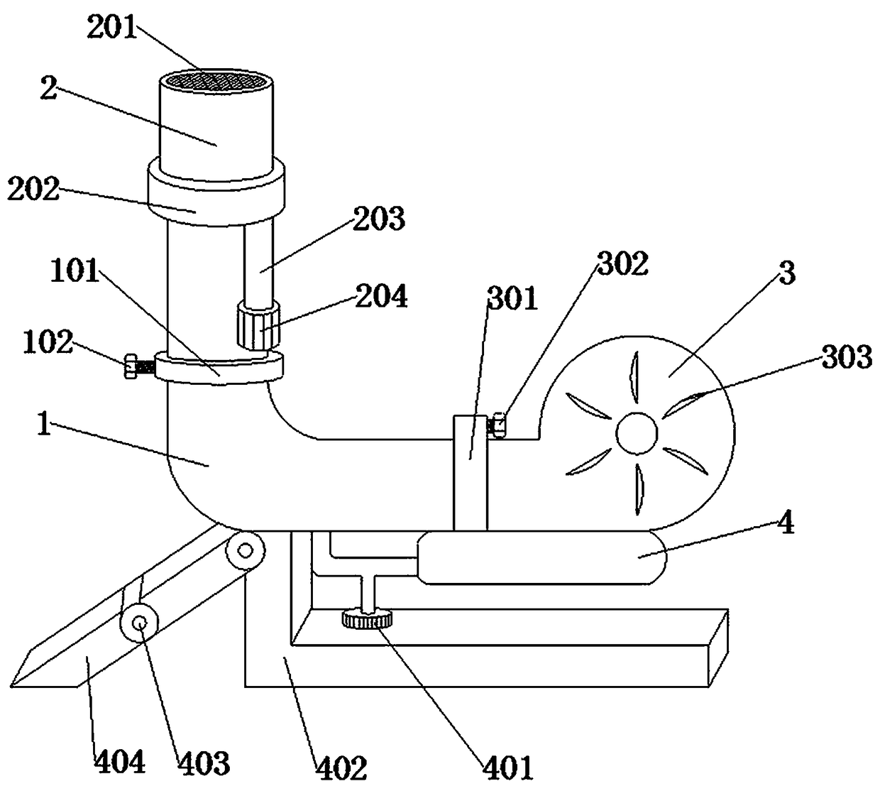
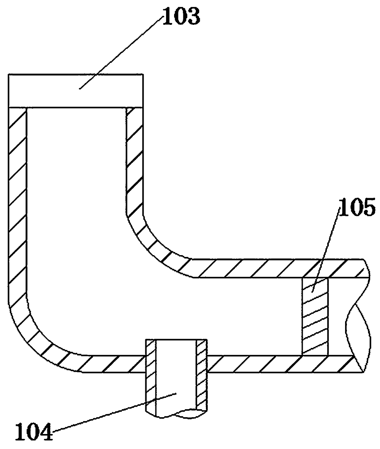
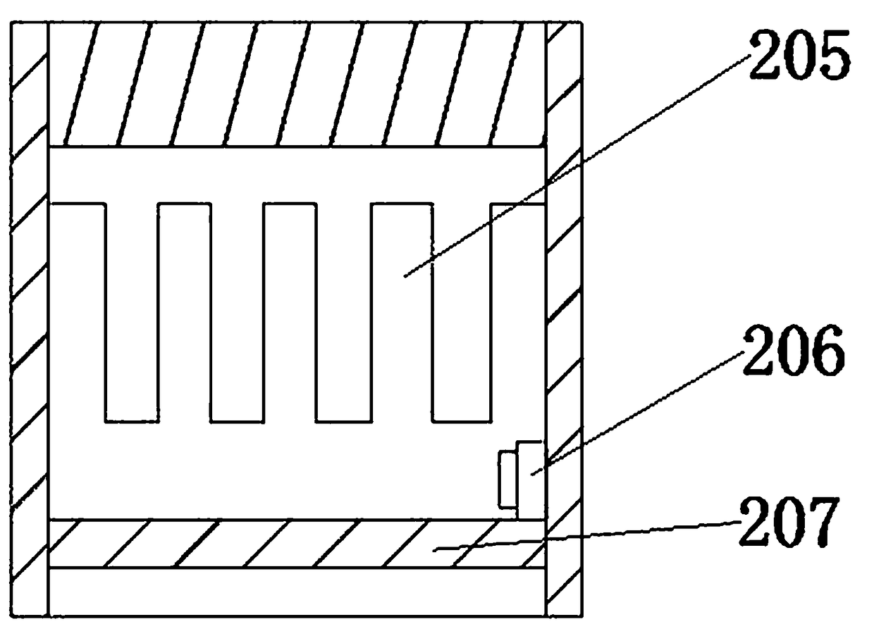
[0027] see Figure 1-4 , the present invention provides a technical solution: an energy-saving and environmentally friendly gas burner, comprising a gas mixing chamber 1, a combustion chamber 2 and a blower 3, an adjustment ring 101 is sleeved above the gas mixing chamber 1, and the adjustment ring 101 can be along the gas The mixing chamber 1 rotates in the axial direction to realize flexible adjustment. The upper part of the adjustment ring 101 is connected with the combustion chamber 2, and the combustion chamber 2 is in the shape of a "cylinder", which is more stable. The outer wall of the combustion chamber 2 is sleeved with a cleaning swivel 202 , an ignition tube 203 is connected through the inside of the cleaning swivel 202, and the ignition tube 203 is a high-temperature resistant insulating material to ensure the safety of the device. An ignition control button 204 is sleeved at the end of the ignition tube 203 away from the cleaning swivel 202, and the gas is mixed. ...

Embodiment 2

[0029]In an embodiment, an energy-saving and environment-friendly gas burner includes a gas mixing chamber 1, a combustion chamber 2, and a blower 3. An adjusting ring 101 is sleeved above the gas mixing chamber 1, and the adjusting ring 101 can move along the axis of the gas mixing chamber 1. Rotate in the central direction to achieve flexible adjustment. The top of the adjustment ring 101 is connected with the combustion chamber 2, and the combustion chamber 2 is in the shape of a "cylinder", which is more stable. The outer wall of the combustion chamber 2 is sleeved with a cleaning swivel 202. The cleaning swivel The interior of 202 is connected with an ignition tube 203, and the ignition tube 203 is made of high temperature resistant insulating material to ensure the safety of the device. The end of the ignition tube 203 away from the cleaning swivel 202 is sleeved with an ignition control button 204, and the gas mixing chamber 1 is far away from the adjustment One side of ...

Embodiment 3

[0032] In an embodiment, an energy-saving and environment-friendly gas burner includes a gas mixing chamber 1, a combustion chamber 2, and a blower 3. An adjusting ring 101 is sleeved above the gas mixing chamber 1, and the adjusting ring 101 can move along the axis of the gas mixing chamber 1. Rotate in the central direction to achieve flexible adjustment. The top of the adjustment ring 101 is connected with the combustion chamber 2, and the combustion chamber 2 is in the shape of a "cylinder", which is more stable. The outer wall of the combustion chamber 2 is sleeved with a cleaning swivel 202. The cleaning swivel The interior of 202 is connected with an ignition tube 203, and the ignition tube 203 is made of high temperature resistant insulating material to ensure the safety of the device. The end of the ignition tube 203 away from the cleaning swivel 202 is sleeved with an ignition control button 204, and the gas mixing chamber 1 is far away from the adjustment One side of...


PUM


Abstract

The invention discloses an energy-saving and environment-friendly fuel gas burner. The energy-saving and environment-friendly fuel gas burner comprises a fuel gas mixing chamber, a combustion chamberand an air blower, wherein an adjusting ring is connected above the fuel gas mixing chamber in a sleeved mode, the combustion chamber is arranged above the adjusting ring in a penetrating mode, and acleaning rotating ring is connected to the outer wall of the combustion chamber in a sleeved mode; the interior of the cleaning rotating ring is connected with an ignition tube in a penetrating mode,one end, away from the cleaning rotating ring, of the ignition tube is connected with an ignition control button in a sleeved mode, one end, away from the adjusting ring, of the fuel gas mixing chamber is sleeved with an air regulating ring, and one side, away from the fuel gas mixing chamber, of the air regulating ring is connected with the air blower in a penetrating mode; and the interior of the air regulating ring is movably connected with a telescopic ring, and the outer wall of the telescopic ring is connected with a sleeve ring in a sleeved mode. The fuel gas burner is a device for converting a heat energy through a chemical reaction mode of burning a substance, namely air and fuel are mixed and blended according to a proper proportion through a premixing device so that the air andthe fuel can be fully combusted, the combustor is used for feeding fuel and air into a hearth according to the required concentration, speed, turbulence degree and mixing mode.

Description

technical field [0001] The invention relates to the field of burners, in particular to an energy-saving and environment-friendly gas burner. Background technique [0002] A gas burner is a kind of equipment that converts substances into heat energy through the chemical reaction of combustion, that is, air and fuel are mixed in an appropriate proportion through a premixing device to make it fully burned. The burner is a kind of fuel and air. , into the furnace according to the required concentration, speed, turbulence and mixing mode, and make the fuel stably ignite and burn in the furnace. The orderly operation of the system can realize the full combustion of the burner fuel, which is generally used in small and medium-sized oil-fired or gas-fired boilers. However, in the current technology, the environmental protection and energy saving of the gas burner cannot be realized, the burner cannot be stably fixed, and the air volume in the air supply system cannot be flexibly ad...

Claims


Application Information

Patent Timeline
Patent Type & Authority Applications(China)
IPC IPC(8): F23D14/02F23D14/14F23D14/28F23D14/34F23D14/62F23D14/60F23D14/68F23D14/46
CPCF23D14/02F23D14/14F23D14/28F23D14/34F23D14/46F23D14/60F23D14/62F23D14/68
Inventor 李春生
Owner DIMENSION TECH
Why Eureka
Try Eureka