High-speed Raman spectroscopy scanning imaging method and device with three-dimensional high spatial resolution

A high spatial resolution, Raman spectroscopy technology, applied in Raman scattering, material excitation analysis, etc., can solve the problem of image lateral resolution and axial resolution improvement, Raman spectroscopy imaging speed is slow, point-by-point scanning time Long and other problems, to achieve the effect of eliminating stray light, improving the speed of multi-focus scanning imaging, and good monochromaticity

Active Publication Date: 2021-01-22
武汉菲谱光电技术有限公司
View PDF6 Cites 0 Cited by
  • Summary
  • Abstract
  • Description
  • Claims
  • Application Information

AI Technical Summary

Problems solved by technology

This makes the image lateral resolution and axial resolution of the micro-Raman spectrometer cannot be improved by using a liquid immersion objective lens.
In addition, since the Raman light excited by the sample to be measured is very weak, the detector in the spectrometer must be exposed for a long time to collect a Raman signal of sufficient intensity
This makes the microscope imaging system in the micro-Raman spectrometer take a long time to scan point by point, and the Raman spectrum imaging speed is relatively slow.

Method used


Image

  • High-speed Raman spectroscopy scanning imaging method and device with three-dimensional high spatial resolution
  • High-speed Raman spectroscopy scanning imaging method and device with three-dimensional high spatial resolution
  • High-speed Raman spectroscopy scanning imaging method and device with three-dimensional high spatial resolution

Examples


Embodiment 1

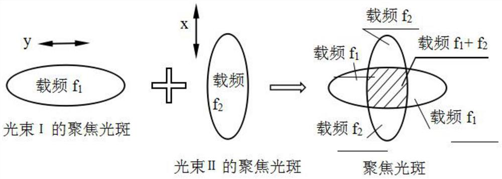
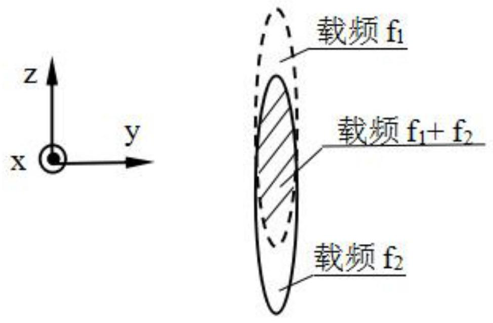
[0047] If the optical system is illuminated by linearly polarized coherent light, for a high numerical aperture optical system, the distribution of focused spots on the focal plane is significantly affected by the polarization characteristics of the illuminating light. like figure 1 As shown, if linearly polarized coherent light in the y direction is used for illumination, the focused spot on the focal plane is distributed in an ellipse, and the minor axis of the ellipse is perpendicular to the direction of the linearly polarized light (the y direction at this time), that is, the ellipse at this time The minor axis direction is along the x direction. If linearly polarized coherent light in the x direction is used for illumination, the short axis direction of the elliptical focused spot on the focal plane is along the y direction. The lateral resolution of the optical system depends on the size of the focused spot. Obviously, if the linearly polarized coherent light in the y ...

Embodiment 2

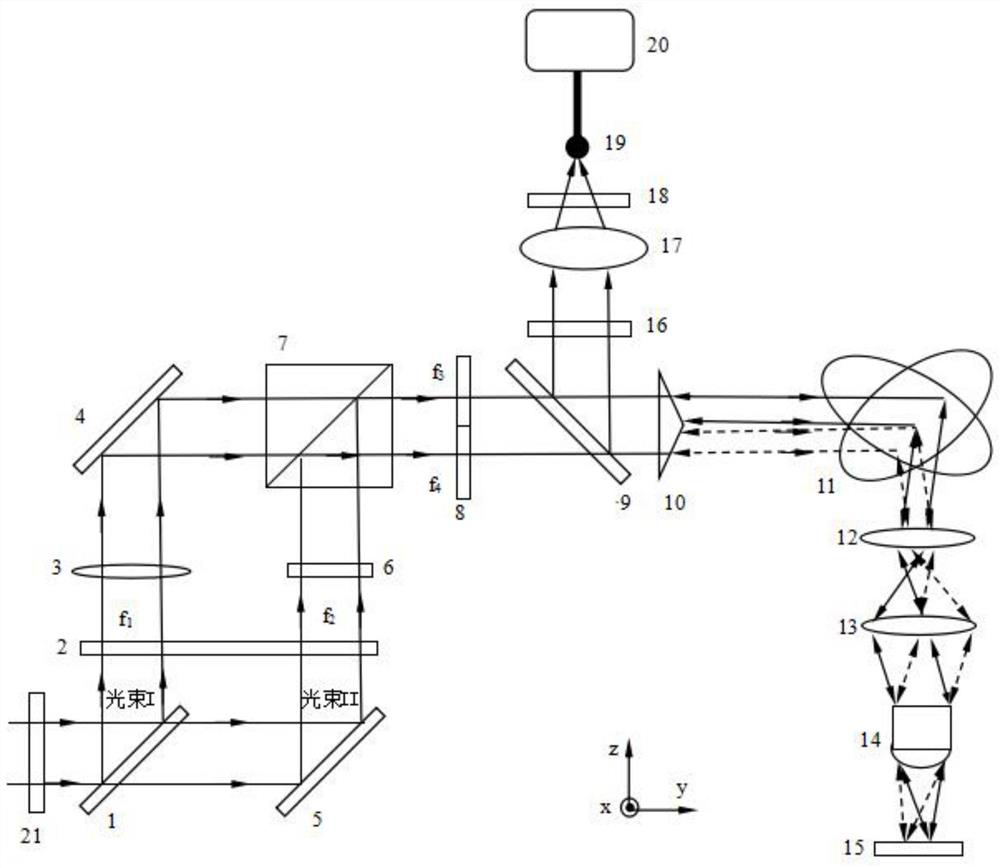
[0086] like Figure 5 As shown, the incident light g and the refracted light are g1 and g2, if the included angles between the two facets m1 and m2 of the prism 8 and the bottom surface are respectively θ 1 and θ 2 , the refractive index of the prism 9 is n, then the angle between the refracted light g1 of the facet m1 and the first optical axis (z axis) can be obtained as θ 1 '=asin(nsinθ 1 -θ 1 ),like Image 6 As shown, the distance h from the focused spot A to the fifth optical axis (x-axis) 1 =fsin[asin(nsinθ 1 -θ 1 )], where f is the focal length of the focusing objective lens 2. Similarly, the distance h from the focused spot B to the fifth optical axis 2 =fsin[asin(nsinθ 2 -θ 2 )]. Therefore, the position of the focused spot can be precisely controlled by the refractive index n of the prism, the angles between the facets m1 , m2 and the z-axis, and the focal length f of the focusing lens 13 . If the planes m1 and m2 are asymmetrical about the first optical a...

Embodiment 3

[0088] This embodiment is the same as other structures and settings in Embodiment 1, except that the polyhedral prism has been replaced by Figure 7 Polyhedral prism shown at center left. The polyhedral prism is a tetrahedron cylinder prism with a bottom surface and three prisms, and the three prisms are arranged symmetrically along the first optical axis.

[0089] In this embodiment, the focus spot distribution is as follows: on the sample 15, such as Figure 7 The three focused spots on the middle right are aligned along the y-axis in the xy-plane. If the facet is perpendicular to the light beam g and arranged symmetrically along the first optical axis, the focused light spot obtained by passing through the facet is on the origin of the coordinate axis.

[0090] Further, assuming that the confocal scanning imaging finally needs to obtain an image of n rows and n columns, and the polyhedral prism of this embodiment is used to generate 3 points of column distribution focal p...


PUM


Abstract

Disclosed in the invention are a three-dimensional high-spatial-resolution high-speed Raman spectroscopy scanning imaging method and device. The device comprises a narrowband filter, a beam splitter,a first frequency modulator, a first reflector, a second reflector, a one-second wave plate, a polarization beam splitting prism, a second frequency modulator, a dichroic beam combiner, a polyhedron prism, a two-dimensional vibration mirror, a first lens unit, a focusing objective, a filter, a second lens unit, an aperture, an optical fiber, and a spectrometer. According to the invention, two beams of orthogonal linear polarized light are constructed at the same time for illumination; frequency modulation is used to distinguish the overlap of a light spot formed by the focusing of the linear polarized light; the purpose of increasing the speed of multi-focus scanning imaging is realized by using the polyhedron prism; and frequency demodulation of the spectrometer is used to extract effective signals corresponding to an overlapping region of the light spot formed by the focusing of the two beams of orthogonal linear polarized light. Therefore, three-dimensional spatial resolution is increased and high resolution Raman spectroscopy scanning imaging is realized by the narrowband filter and the filter blocking scattering light and stray light.

Description

technical field [0001] The invention belongs to the field of optical technology, and in particular relates to a high-speed Raman spectrum scanning imaging method and device with three-dimensional high spatial resolution. Background technique [0002] Due to its non-contact and non-destructive characteristics, optical imaging is widely used in research fields such as life science and material science. The optical resolution is an important indicator of the optical imaging system, usually the higher the resolution, the better. Optical resolution includes lateral resolution and axial resolution, which limit each other. That is, the higher the lateral resolution, the lower the axial resolution; the higher the axial resolution, the lower the lateral resolution. Therefore, how to improve the lateral resolution and axial resolution is the goal of researchers' continuous efforts. It has important application value if high lateral resolution and high axial resolution can be realiz...

Claims


Application Information

Patent Timeline
Patent Type & Authority Patents(China)
IPC IPC(8): G01N21/65
CPCG01N21/65
Inventor 郭汉明黄斐郑思旭王俊炜薛萌杨照清贾仕达王秀花胡金兵
Owner 武汉菲谱光电技术有限公司
Why Eureka
Try Eureka