Target arrival angle estimation method based on spatial discrete grid dynamic update

A technology of spatial dispersion and angle estimation, which is applied in directions such as direction finders using radio waves, radio wave direction/bias determination systems, etc. In order to achieve high estimation accuracy and reduce computational complexity,

Active Publication Date: 2018-12-21
HARBIN ENG UNIV
View PDF6 Cites 16 Cited by
  • Summary
  • Abstract
  • Description
  • Claims
  • Application Information

AI Technical Summary

Problems solved by technology

Usually, in order to avoid or reduce the influence of discrete grid errors as much as possible, it is necessary to use dense spatial grid division as much as possible. However, dense grid division cannot fully guarantee that the real target arrival angle falls on the discretely divided grid points. Moreover, as the discrete grid division becomes denser, the large increase in the number of discrete grid points will increase the computational complexity
In the spectral search algorithm, a finer search is usually performed near the spectral peak obtained on the initial grid, which will improve the discrete grid mismatch problem of the search algorithm to a certain extent, but it cannot fundamentally eliminate discrete grid error
Sparse reconstruction algorithms mainly construct sparse dictionaries on finite discrete spatial grids. Similarly, no matter how dense the network division is, it cannot guarantee that the target is included in the discrete grid. In addition, too dense spatial grids will lead to sparse Increased relevance of dictionaries
According to the constraint equidistant condition, the recovery effect of the sparse reconstruction algorithm is the best when the correlation of the sparse dictionary is low. As the correlation of the column vector of the sparse dictionary increases, the recovery effect of the sparse reconstruction algorithm will become worse.

Method used


Image

  • Target arrival angle estimation method based on spatial discrete grid dynamic update
  • Target arrival angle estimation method based on spatial discrete grid dynamic update
  • Target arrival angle estimation method based on spatial discrete grid dynamic update

Examples


Embodiment Construction

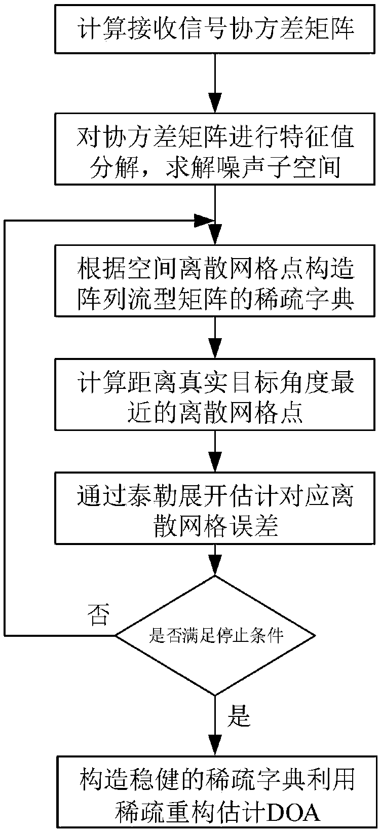
[0062] Below in conjunction with accompanying drawing, method provided by the present invention is described in more detail:

[0063] Step 1. Calculate the covariance matrix of the array antenna

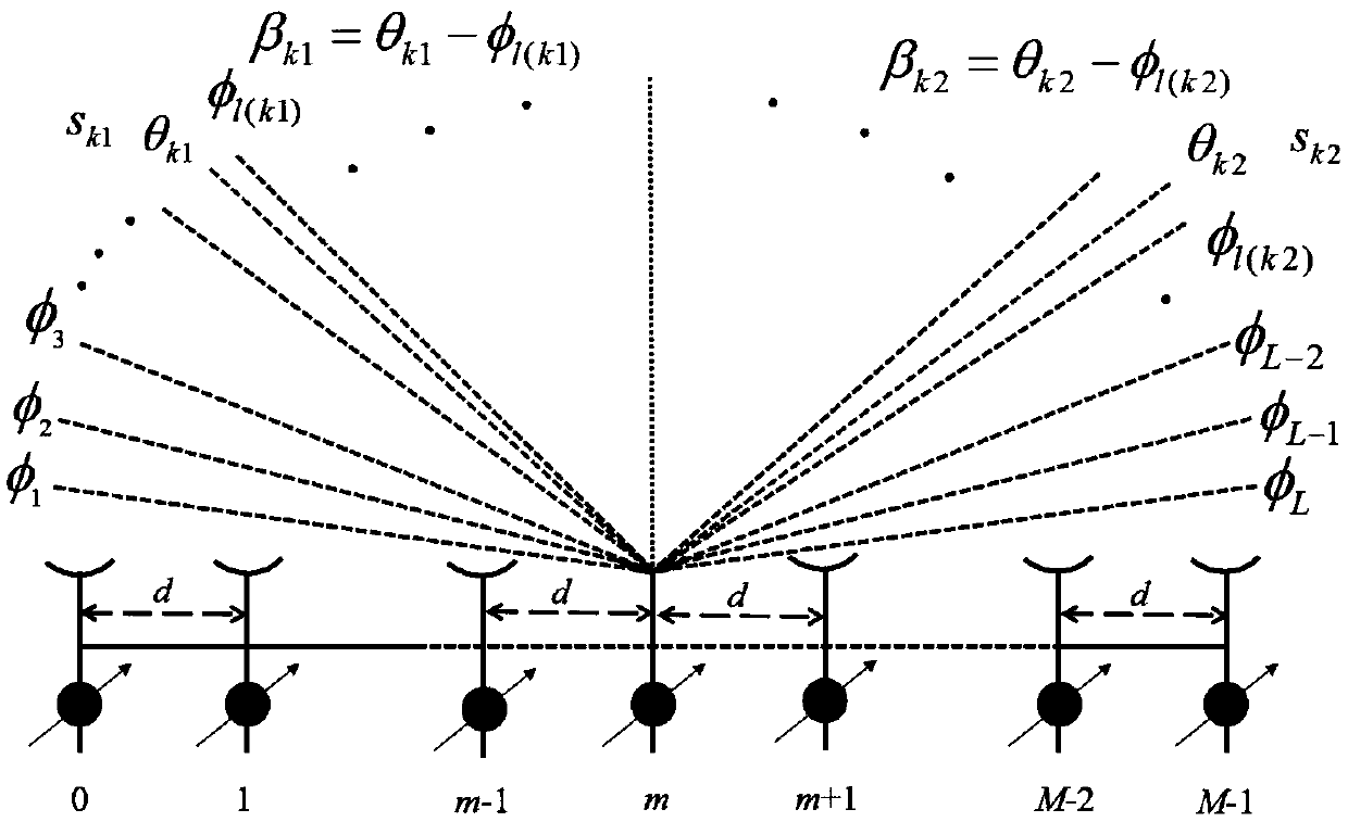
[0064] Assume that the antenna element position of the uniform linear array is d=[d 0 , d 1 ,...,d M-1 ] T , not generally assuming that the first antenna is d 0 = 0, then d m =(m-1)d. If there are K far-field and uncorrelated targets irradiated on the line array, assuming that the incoming wave direction of the target is θ=[θ 1 ,θ 2 ,...,θ K ] T , where θ k is the incoming wave direction of the kth target, then the baseband received signal of the target under the tth snapshot can be expressed as:

[0065]

[0066] in is the steering vector corresponding to the kth target, A=[a(θ 1 ),...,a(θ K )] is the array flow matrix. n(t) is additive Gaussian white noise with mean value of 0 and variance of

[0067] According to the received signal mathematical model given ...


PUM


Abstract

The invention provides a target arrival angle estimation method based on spatial discrete grid dynamic update, and belongs to the technical field of array signal processing. The target arrival angle estimation method is mainly for solving the problem of spatial discrete grid mismatch faced in the DOA estimation process on an array signal processing problem. Eigenvalue decomposition is performed ona signal sampling covariance matrix, through a basis pursuit method, a discrete point closest to a real angle is found, then the discrete grid points are dynamically updated by iteration, so that thediscrete grid points continuously approach a true DOA value of a target, and accurate estimation of multiple target arrival angles is carried out. The target arrival angle estimation method based onthe spatial discrete grid dynamic update effectively solves the problem of the spatial discrete grid mismatch by using a spatial discrete grid dynamic learning method, so that the algorithm can quickly estimate the DOA and keep a quite high target estimation accuracy even if the step size of a spatial discrete grid is large.

Description

technical field [0001] The invention relates to a method for estimating an angle of arrival of a target based on a dynamic update of a space discrete grid on a uniform linear array, and belongs to the technical field of array signal processing. Background technique [0002] Array signal processing technology uses multiple sensors for signal measurement, thereby using the spatial characteristics of the signal to obtain additional spatial domain freedom. Compared with traditional one-dimensional signal processing technology, it has the advantages of higher signal gain, strong anti-interference, and high resolution. . After years of development, array signal processing technology has been successfully applied in fields such as astronomical observation, radar, sonar, communication system and biomedicine. Array signal processing technologies mainly include adaptive beamforming technology and high-resolution spatial spectrum estimation technology. Estimation of target angle of a...

Claims


Application Information

Patent Timeline
Patent Type & Authority Applications(China)
IPC IPC(8): G01S3/14
CPCG01S3/14
Inventor 王伟魏震宇王犇董福王龚琳舒李欣黄平
Owner HARBIN ENG UNIV
Why Eureka
Try Eureka