A vacuum transfer device

A technology of vacuum transmission and vacuum chamber, which is applied in the direction of transportation and packaging, conveyor objects, sustainable manufacturing/processing, etc., and can solve the problems of unstable adsorption of cells

Active Publication Date: 2020-10-23
48TH RES INST OF CHINA ELECTRONICS TECH GROUP CORP
View PDF3 Cites 0 Cited by
  • Summary
  • Abstract
  • Description
  • Claims
  • Application Information

AI Technical Summary

Problems solved by technology

However, with this structure, during the transportation of the cells, the vacuum chamber consumes much more vacuum than the vacuum provided by the vacuum generator, resulting in unstable cell adsorption.

Method used


Image

  • A vacuum transfer device
  • A vacuum transfer device
  • A vacuum transfer device

Examples


Embodiment Construction

[0032] The present invention will be described in further detail below in conjunction with the accompanying drawings and specific embodiments.

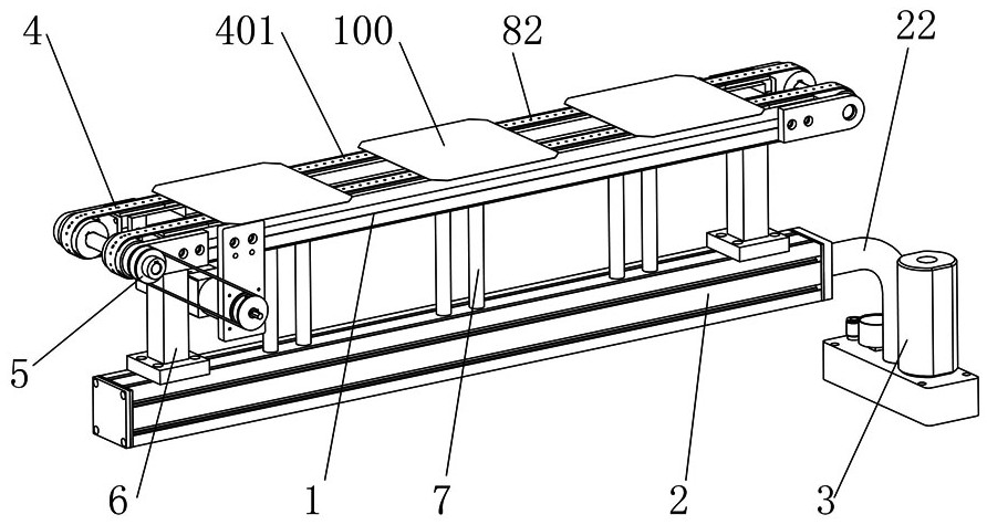
[0033] The vacuum conveying device of the present invention is mainly used for conveying battery sheets 100 .

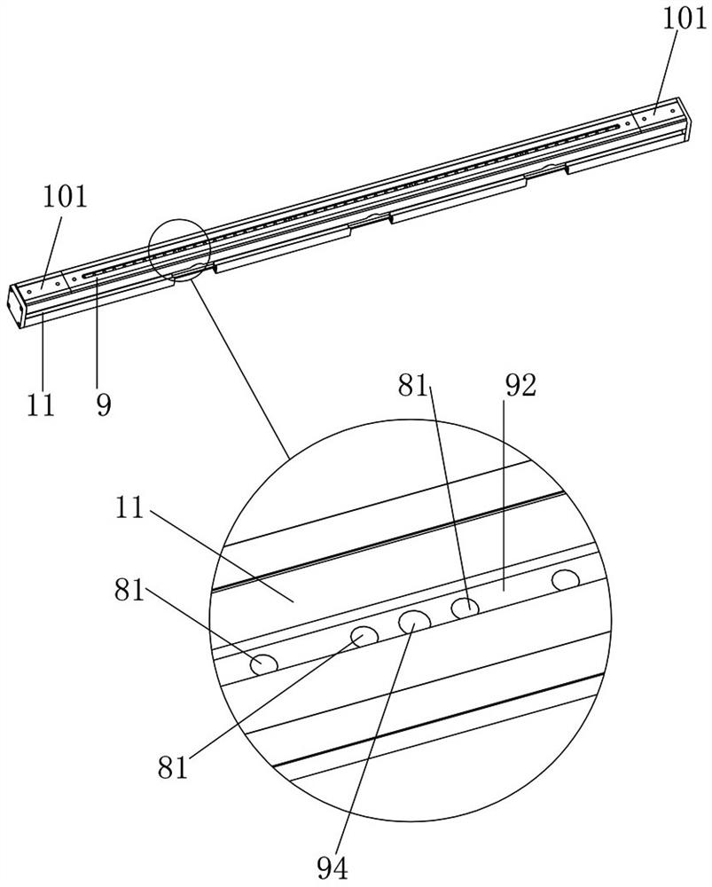
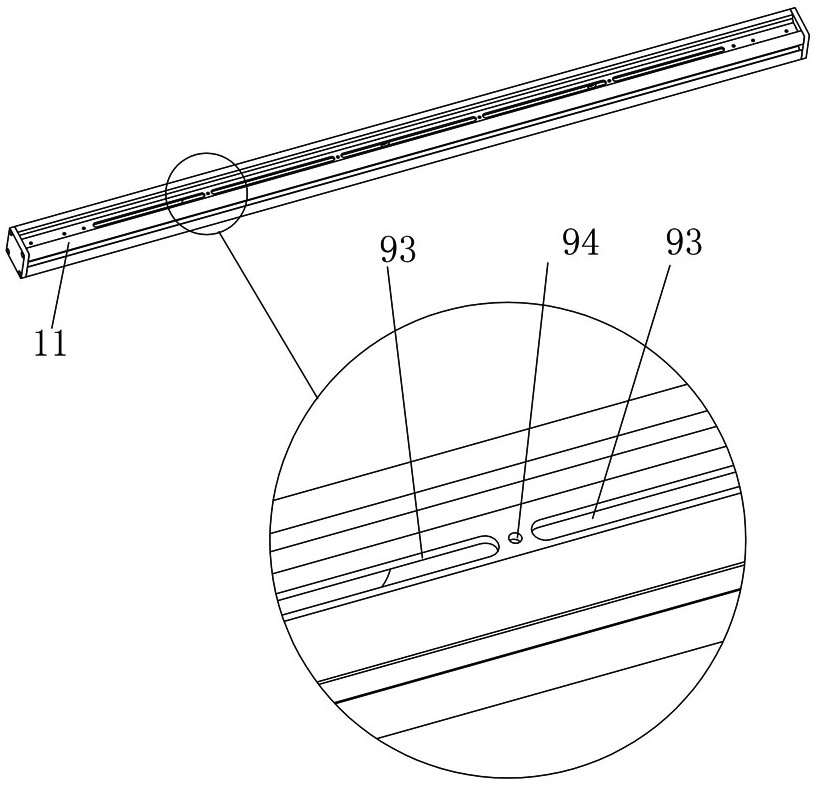
[0034] Such as Figure 1 to Figure 7 As shown, the vacuum transfer device of this embodiment includes a transfer assembly, a first vacuum chamber 1, a second vacuum chamber 2 and a vacuum generator 3, and the transfer assembly includes a conveyor belt 4 and a transmission drive mechanism that drives the conveyor belt 4 to rotate 5. The first vacuum chamber 1 is located below the conveying section 401 of the conveyor belt 4, and is attached to the conveying section 401. The first vacuum chamber 1 and the second vacuum chamber 2 are connected by a support assembly 6, and the two The other is connected through the connecting pipe 7, the vacuum generator 3 is connected with the second vacuum chamber 2, and the surface of the co...


PUM


Abstract

The invention discloses a vacuum transmission device comprising a transmission assembly, a first vacuum chamber, a second vacuum chamber and a vacuum generator. The transmission assembly consists of aconveyor belt and a conveying drive mechanism for driving the rotation of the conveyor belt. The first vacuum chamber is arranged below the conveying section of the conveyor belt and is in contact with the conveying section; and the first vacuum chamber and the second vacuum chamber are connected by a support assembly and are communicated by a connecting pipe. The vacuum generator and the secondvacuum chamber are communicated. Vacuum adsorption hole are formed in the surface, in contact with the first vacuum chamber, of the conveying section along the conveying direction and are communicatedwith the first vacuum chamber. Therefore, the negative pressure is uniform and stable and the battery sheet can be quickly and smoothly transmitted.

Description

technical field [0001] The invention relates to the field of automation equipment for manufacturing PERC high-efficiency batteries, in particular to a vacuum transmission device. Background technique [0002] In 2015, the photovoltaic leader plan was launched. Through this plan, the country guided the orderly upgrading of the photovoltaic industry. The industry responded positively and took advantage of the trend to accelerate the pace of high-efficiency battery technology from research and development to mass production. After the market crashes, the main high-efficiency cell technologies selected by the photovoltaic industry are: polycrystalline black silicon cell technology, N-type monocrystalline bifacial cell technology and P-type monocrystalline PERC cell technology. [0003] Compared with the conventional single crystal cell process, the PERC single crystal cell mainly adds three processes of rear passivation, rear SiNx film deposition and laser drilling. In recent y...

Claims


Application Information

Patent Timeline
Patent Type & Authority Patents(China)
IPC IPC(8): H01L21/677H01L31/18
CPCH01L21/67706H01L21/67784H01L31/1876Y02P70/50
Inventor 王慧勇肖慧
Owner 48TH RES INST OF CHINA ELECTRONICS TECH GROUP CORP
Why Eureka
Try Eureka