A P-type SE-PERC double-sided solar cell and a preparation method thereof

A solar cell, double-sided technology, applied in the field of solar cells, can solve the problems of inaccuracy and deformation of the alignment of the front silver sub-grid electrode and the laser doped region, so as to enhance the short-wave response, improve the photoelectric conversion efficiency, and improve the output capability. Effect

Pending Publication Date: 2018-12-21
ZHEJIANG AIKO SOLAR ENERGY TECH CO LTD +1
View PDF0 Cites 21 Cited by
  • Summary
  • Abstract
  • Description
  • Claims
  • Application Information

AI Technical Summary

Problems solved by technology

[0006] One of the objectives of the present invention is to provide a P-type SE-PERC double-sided solar cell. After the front side of the solar cell is diffused, a number of parallel laser grooves are formed by laser doping. The design of the groove area or the design of the groove area with different widths can solve the problem of misalignment between the front silver sub-gate electrode and the laser doped area caused by the deformation of the front silver electrode screen during the printing process, and improve the stability of mass production of batteries

Method used


Image

  • A P-type SE-PERC double-sided solar cell and a preparation method thereof
  • A P-type SE-PERC double-sided solar cell and a preparation method thereof
  • A P-type SE-PERC double-sided solar cell and a preparation method thereof

Examples


Embodiment 1

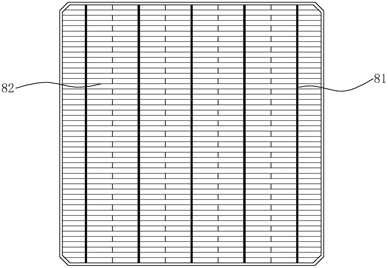
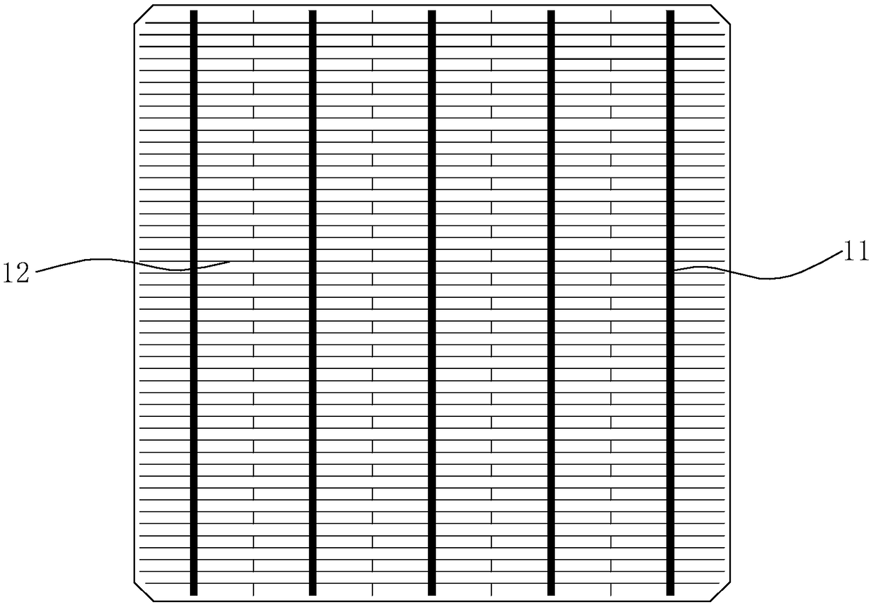
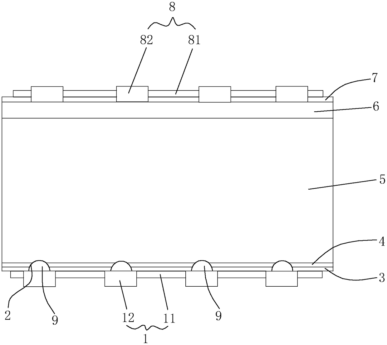
[0046] Embodiments of the P-type SE-PERC double-sided solar cell of the present invention are as follows Figure 1 to Figure 4 As shown, it includes a back electrode 1, a back silicon nitride film 3, a back aluminum oxide film 4, a P-type silicon 5, an N-type silicon 6, a front silicon nitride film 7 and a front silver electrode 8 arranged in sequence from bottom to top. The silver electrode 8 is composed of a front silver main grid electrode 81 made of silver and a front silver sub grid electrode 82 made of silver. The front silver sub grid electrode 82 is perpendicular to the front silver main grid electrode 81. The back electrode 1 is made of silver material. The back silver main gate electrode 11 and the back aluminum sub-gate electrode 12 made of aluminum, the back aluminum sub-gate electrode 12 and the back silver main gate electrode 11 are perpendicular to each other.

[0047]On the back of the solar cell, there is also a laser groove area 2 on the back after opening th...

Embodiment 2

[0067] The difference between Embodiment 2 and Embodiment 1 of the P-type SE-PERC double-sided solar cell of the present invention is that, as Figure 5 As shown, in the second embodiment, several laser grooves 10 are designed with grooved areas with different widths, and the width of the laser grooves 10 gradually widens from the middle to both sides. The width of the laser groove 10 is in the range of 80-300um. The laser groove 10 in the middle is the narrowest, with a width of 80um, the laser groove 10 on the outermost two sides is the widest, with a width of 300um, and the distance between adjacent laser grooves 10 is equal to 1.2mm. The distance between 10 can also be selected within the range of 0.8-2 mm. The preparation method of embodiment two is the same as embodiment one.


PUM


Abstract

The invention discloses a P-type SE-PERC double-sided solar cell and preparation method thereof, the solar cell includes back electrodes arranged sequentially from bottom to top, A back side silicon nitride film, back alumina film, P-type silicon, N-type silicon, A front silicon nitride film and a positive silver electrode, the front surface of the n-type silicon is formed with a plurality of laser grooves parallel to each other by laser doping after diffusion and before depositing the front surface silicon nitride film, the laser slots are designed with slotted areas with different spacing orwith different slotted areas with different width, the number of laser grooves is equal to the number of positive silver sub-gate electrodes, and one-to-one correspondence, when etching the positivesilver electrode with the positive silicon nitride film, the paste falls in the laser groove to form the positive silver sub-gate electrode, thereby solving the problem that the positive silver sub-gate electrode is not aligned with the laser doped region due to the deformation of the positive silver electrode screen plate in the printing process, and improving the stability of batch production ofthe battery. The invention also discloses a preparation method of the solar cell.

Description

technical field [0001] The invention relates to the technical field of solar cells, in particular to a P-type SE-PERC double-sided solar cell and a preparation method thereof. Background technique [0002] Crystalline silicon solar cell is a device that effectively absorbs solar radiation energy and converts light energy into electrical energy by using the photovoltaic effect. Under the action, holes flow from the N region to the P region, electrons flow from the P region to the N region, and a current is formed after the circuit is turned on. [0003] Traditional crystalline silicon solar cells basically only use front passivation technology, depositing a layer of silicon nitride film on the front surface of the silicon wafer by PECVD to reduce the recombination rate of minority carriers on the front surface, which can greatly increase the open circuit voltage and Short-circuit current, thereby improving the photoelectric conversion efficiency of crystalline silicon solar ...

Claims


Application Information

Patent Timeline
Patent Type & Authority Applications(China)
IPC IPC(8): H01L31/068H01L31/18
CPCH01L31/0684H01L31/1804Y02E10/547Y02P70/50
Inventor 林纲正方结彬何达能陈刚
Owner ZHEJIANG AIKO SOLAR ENERGY TECH CO LTD
Why Eureka
Try Eureka