
Image acquisition device and image acquisition method

A technology for obtaining devices and images, applied in the field of image devices, to achieve the effect of improving the SN ratio

Active Publication Date: 2018-12-21
HAMAMATSU UNIV SCHOOL OF MEDICINE +1
View PDF14 Cites 0 Cited by
  • Summary
  • Abstract
  • Description
  • Claims
  • Application Information

AI Technical Summary

Problems solved by technology

Originally, if a single-point scan is performed, there is no need to perform a multi-point scan

Method used


Image

  • Image acquisition device and image acquisition method
  • Image acquisition device and image acquisition method
  • Image acquisition device and image acquisition method

Examples


Embodiment Construction

[0046] Hereinafter, modes for implementing the present invention will be described in detail with reference to the drawings. In addition, in description of drawings, the same code|symbol is attached|subjected to the same element, and repeated description is abbreviate|omitted. In addition, this invention is not limited to these illustrations.

[0047] The image acquisition device and image acquisition method of the present embodiment can acquire images of fluorescence, harmonic light, reflected scattered light, etc. generated on the surface or inside of the object to be observed. Image implementations are described. In addition, in each figure, the xyz rectangular coordinate system is shown for the convenience of description of the relationship etc. of an observation object and the direction of light irradiation.

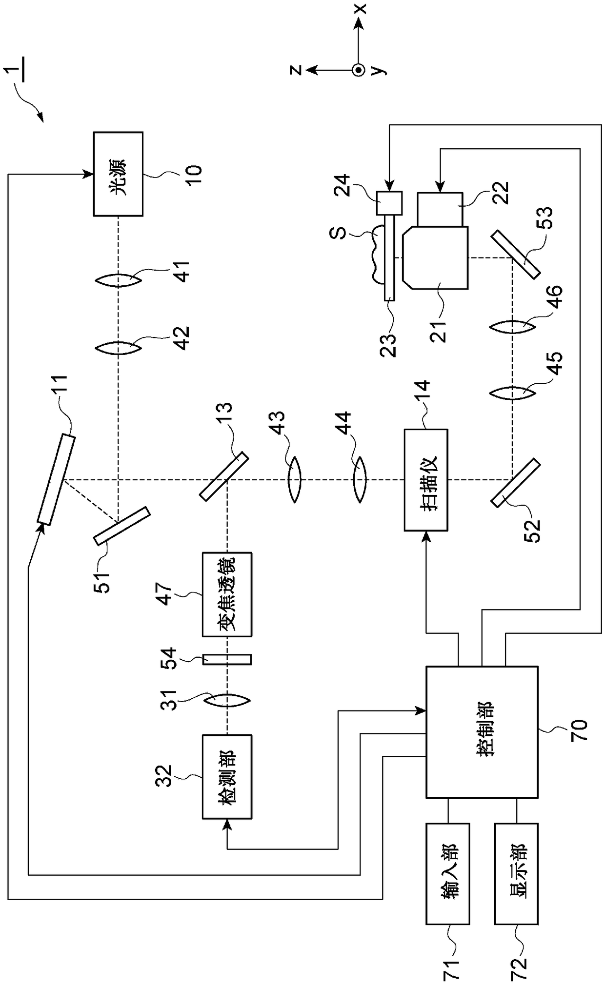
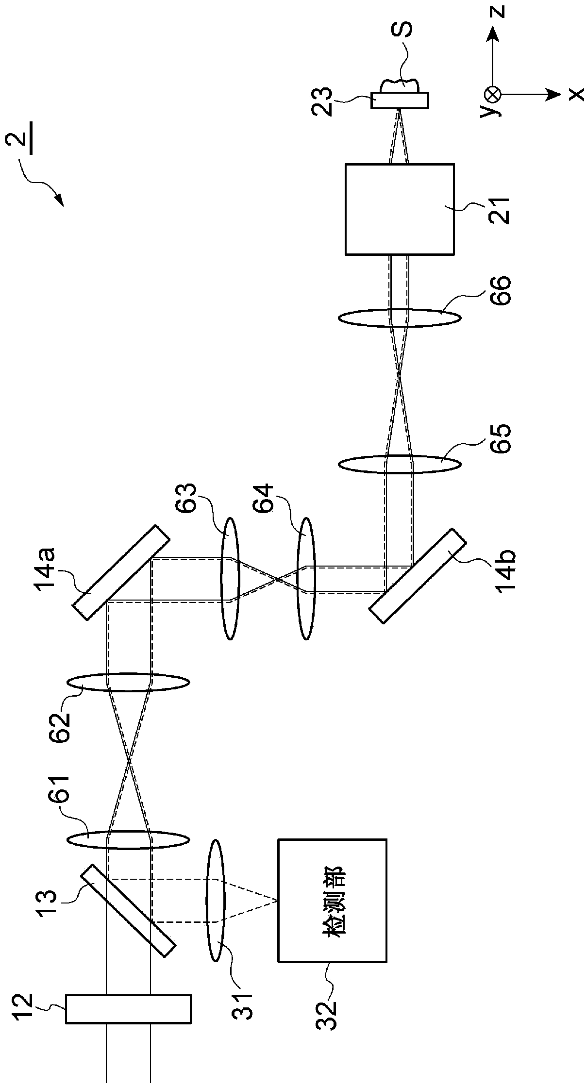
[0048] figure 1 It is a diagram showing the configuration of the image acquisition device 1 . The image acquisition device 1 includes a light source 10 , a spat...


PUM


Abstract

This image acquisition device 1 is provided with a spatial optical modulator 11, an optical scanner 14, a detection unit 32, a control unit 70 and so forth. The spatial optical modulator 11 irradiatesa plurality of irradiation areas on the surface or inside of a subject to be observed S with focused modulated excitation light. The detection unit 32 has on the light receiving plane thereof a plurality of imaging areas that establishes an imaging relationship with the plurality of irradiation areas of the subject to be observed through an imaging optical system. Each of the plurality of imagingareas corresponds to one or more pixels, and pixels that correspond to none of the plurality of imaging areas exist adjacent to each imaging area. The control unit 70 corrects the detection signal ofa pixel corresponding to each imaging area on the basis of the detection signal of a pixel that exists adjacent to the imaging area and corresponds to none of the plurality of imaging areas, and creates an image of the observed subject on the basis of the corrected detection signal. This makes it possible to achieve an image acquisition device and an image acquisition method with which the SN ratio of an observed subject image generated by multi-point scanning can be easily improved.

Description

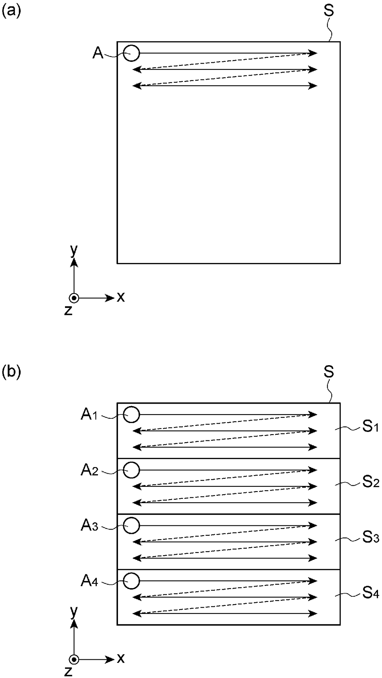
technical field [0001] One aspect of the present invention relates to manufacturing an observation object by condensing light onto a plurality of irradiation areas on the surface or inside of an observation object, scanning the plurality of irradiation areas, and detecting the light generated in each of the plurality of irradiation areas. Image apparatus and method. Background technique [0002] The image acquisition devices described in Non-Patent Documents 1 and 2 can condense light onto a plurality of irradiation areas on the surface or inside of an object to be observed, scan these plurality of irradiation areas, and detect light generated in each of these plurality of irradiation areas. Light (such as fluorescence, high-order harmonic light, reflected scattered light, etc.) is used to create an image of the object to be observed. Compared with the case of scanning a single irradiation area by a single irradiation beam (hereinafter referred to as "single-point scanning"...

Claims


Application Information

Patent Timeline
Patent Type & Authority Applications(China)
IPC IPC(8): G02B21/06G01N21/64
CPCG01N21/64G02B21/06G02B21/367G02B23/26G01N21/6456G01N2021/6463G01N2201/0675G01N2201/121G02B21/0032G02B21/0076G02B21/025G02B21/361
Inventor 松本直也冈崎茂俊
Owner HAMAMATSU UNIV SCHOOL OF MEDICINE
Learn More