Biomass tar combustion system and method

A combustion system and combustion method technology, applied in coke ovens, petroleum industry, special forms of dry distillation, etc., can solve problems such as pyrolysis tar that is difficult to handle

Pending Publication Date: 2018-12-25
ACADEMY OF PLANNING & DESIGNING OF THE MINIST OF AGRI
View PDF3 Cites 5 Cited by
  • Summary
  • Abstract
  • Description
  • Claims
  • Application Information

AI Technical Summary

Problems solved by technology

[0005] The purpose of the present invention is to provide a biomass tar combustion system to solve the difficult problem of pyrolysis tar in pyrolysis charcoal-gas-oil co-production project

Method used


Image

  • Biomass tar combustion system and method
  • Biomass tar combustion system and method
  • Biomass tar combustion system and method

Examples


Embodiment 1

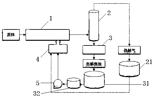
[0037] The storage tank volume of pyrolysis tar is 3m 3 , used for the buffer of pyrolysis tar in the oil production stage, and used for the concentrated combustion of pyrolysis tar.

[0038] Taking the pyrolysis project with a processing capacity of 350kg / h of biomass raw materials as an example, the project runs for 6 hours a day, the tar output is 10kg / h, the calorific value is 30MJ / kg, and the pyrolysis gas output is 150m 3 / h, calorific value is 15MJ / m 3 , adopt oil-based oil-gas co-combustion mode, 1kg tar ratio 1m 3 Pyrolysis gas, that is, in the process of concentrated combustion, 30kg of tar and 30m 3 Pyrolysis gas can meet the needs of equipment. It can realize continuous oil production operation for 16 days, and then focus on burning oil with gas for 6 days, a total of 22 days cycle.

[0039] The technical difficulty of the method of the present invention is: the secondary heating of the tar storage tank and the pipeline is required to ensure better fluidity; in...

Embodiment 2

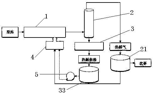
[0048] It is suitable for large-scale pyrolysis projects, with a processing capacity of at least 1t / h, a pyrolysis tar output of more than 30kg / h, and a pyrolysis gas output of 200m 3 / h above. When oil and gas are mixed and burned, the ratio of 1kg of pyrolysis tar is kept at 3m 3 The pyrolysis gas is mixed and burned, and the energy generated is supplied to the front-end pyrolysis equipment, and the excess pyrolysis gas enters the gas storage cabinet for cooking.

[0049] The technical difficulty of the method of the present invention is that the one, must have certain tar production to maintain system operation, and oil production should be more than 30kg / h, just can have a better atomization effect; The 2nd, the continuous separation of oil and water is comparatively difficult, here An oil-water separation tank or centrifuge with insulation can be added, and a small amount of water will not have a great impact on the combustion effect.

[0050] At present, air atomizatio...


PUM

PropertyMeasurementUnit
volumeaaaaaaaaaa
heating valueaaaaaaaaaa

Abstract

The invention discloses a biomass tar combustion system and method, belongs to the technical field of biomass pyrolysis, and aims to solve the problem that pyrolysis oil of pyrolytic carbon gas-oil co-production engineering. The biomass tar combustion system comprises a pyrolysis reaction furnace, a gas-liquid separator, an oil-water separator, a pyrolysis gas buffer tank and a combustor, whereinthe pyrolysis reaction furnace is connected with the gas-liquid separator; the lower end of the gas-liquid separator is connected with the oil-water separator; the upper end of the gas-liquid separator is connected with the pyrolysis gas buffer tank; the oil-water separator is connected with the combustor; and the output end of the combustor is connected with the pyrolysis reaction furnace. The centralized biomass pyrolysis tar combustion system in an embodiment of the invention is simple in technological process and is convenient to operate. A continuous pyrolysis oil-gas cofiring system in another embodiment takes pyrolysis gas as a main combustion material, tar only serves as a combustion-supporting material and is sprayed into the system, combustion is sufficient, fire cut can be avoided, and flue gas discharge reaches the standard easily.

Description

technical field [0001] The invention belongs to the technical field of biomass pyrolysis, and in particular relates to a biomass tar combustion system and method. Background technique [0002] The pyrolysis technology using biomass as raw material can realize clean and efficient conversion of energy. The high-temperature gas produced by biomass pyrolysis is called biomass pyrolysis gas. After dust removal, condensation, decoking and other processes, non-condensable gas is obtained respectively. Substance Fuel gas and condensable gas. The condensable gas is mainly biomass tar, wood vinegar and water vapor, and the main components of biomass gas are CO, CO 2 、H 2 , N 2 、CH 4 etc., because it also contains a certain amount of C 2 h 6 、C 3 h 8 、C 2 h 4 and C 3 h 6 Such macromolecular high calorific value gas has a higher calorific value than biomass pyrolysis gasification gas, which is 15-18MJ / m 3 , can be directly burned for heating equipment. Biomass tar, as a by...

Claims


Application Information

Patent Timeline
Patent Type & Authority Applications(China)
IPC IPC(8): C10B53/00C10B47/00C10B57/00
CPCC10B47/00C10B53/00C10B57/00
Inventor 赵立欣贾吉秀姚宗路丛宏斌孟海波马腾霍丽丽
Owner ACADEMY OF PLANNING & DESIGNING OF THE MINIST OF AGRI
Why Eureka
Try Eureka