
Method for lowering probability of detection dead zones in phase sensitive optical time domain reflection system

A technology of phase-sensitive light and time-domain reflection, applied in the field of optical fiber sensing, can solve problems such as complex methods, improve the accuracy of phase demodulation, and achieve the effect of reducing the false alarm rate of the system

Active Publication Date: 2018-12-25
NANJING UNIV
View PDF4 Cites 13 Cited by
  • Summary
  • Abstract
  • Description
  • Claims
  • Application Information

AI Technical Summary

Problems solved by technology

[0004] In order to eliminate the system false alarm problem caused by interference fading, Fufei Pang et al. proposed a method to eliminate false alarm peaks in "A Fading-Discrimination Method for Distributed Vibration Sensor Using Coherent Detection ofΦ-OTDR" published in IEEEPHOTONICS TECHNOLOGY LETTERS , but did not fundamentally improve the accuracy of phase demodulation
Zhou Jun and others proposed a method based on multi-frequency comprehensive judgment in "Phase demodulation technology based on multi-frequency comprehensive identification of interference fading false signals in Φ-OTDR system" published in the journal "China Laser". Reduce the false alarm rate to a certain extent, but the method is more complicated
At present, there is still a lack of a simple and effective method to correctly extract the phase information from the detection signal containing coherent Rayleigh noise

Method used


Image

  • Method for lowering probability of detection dead zones in phase sensitive optical time domain reflection system
  • Method for lowering probability of detection dead zones in phase sensitive optical time domain reflection system
  • Method for lowering probability of detection dead zones in phase sensitive optical time domain reflection system

Examples


Embodiment Construction

[0022] The technical solutions of the present invention will be described in detail below in conjunction with the accompanying drawings.

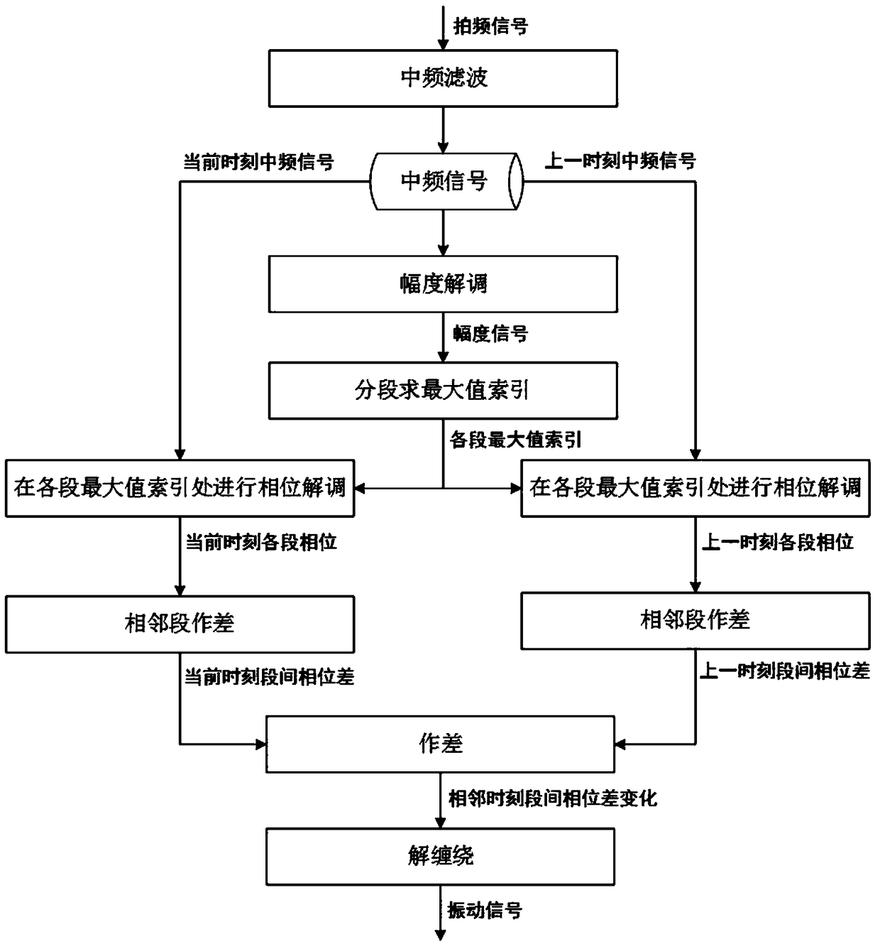
[0023] A specific embodiment of the present invention is provided below, as figure 1 As shown, the specific process is as follows.

[0024] Step 1. Obtain the beat frequency signals of the Rayleigh backscattered light generated by the detection light pulse and the reference light through the Φ-OTDR system of coherent detection. According to the frequency of the beat signal 200MHz and the pulse width of the detection light pulse 100ns, the center frequency of the band-pass filter is specified as 200MHz and the bandwidth is 20MHz. The beat frequency signal is filtered through the band-pass filter to suppress broadband noise and obtain an intermediate frequency signal.

[0025] Step 2. For the Rayleigh backscattering intermediate frequency signal formed by each detection light pulse, by demodulating its IQ amplitude, the distribution of the ...


PUM


Abstract

The invention discloses a method for lowering the probability of detection dead zones in a phase sensitive optical time domain reflection system. The method comprises the steps that medium frequency signals are subjected to amplitude demodulation to obtain the distribution state of amplitudes of the medium frequency signals along with distances; the medium frequency signals at the present are divided into a plurality of intervals on a distance axis, the medium frequency signals with the maximum amplitude index as the center and with the same width as detection optical pulses are selected in each interval to be subjected to phase demodulation to obtain the estimation to all interval phases; the phases of the adjacent intervals are differenced to obtain the optical signal phase difference caused by optical path differences; meanwhile, the phases of the medium frequency signals at the corresponding positions in the previous moment are backtracked, and the phase differences of the adjacentintervals are gained; the phase differences of the current moment and the previous moment are subjected to differentiate operation, the variation of the phase differences of the adjacent intervals isobtained, and winding is released. According to the method, vibration signals can be reconstructed in a high-fidelity mode only by a common single-mode sensing optical fiber without changing a traditional phi-OTDR system structure, and the false alarm rate is obviously lowered.

Description

technical field [0001] The invention belongs to the technical field of optical fiber sensing, and in particular relates to a method for reducing the detection dead zone probability in a phase-sensitive optical time domain reflection system. Background technique [0002] The phase-sensitive optical time-domain reflectometry (Φ-OTDR) sensing system has the advantages of fast response speed and high sensitivity, and can realize distributed detection of weak disturbances. Application prospect. At present, in the research on Φ-OTDR at home and abroad, most of the detection is the intensity information of the Rayleigh scattering signal, and there are few quantitative measurements of the optical phase change caused by external disturbances. Pan Zhengqing and others from Shanghai Institute of Optics and Mechanics used the method of detecting phase to process Φ-OTDR data. This Φ-OTDR based on phase demodulation can obtain a higher signal-to-noise ratio (greater than 10dB) than ampl...

Claims


Application Information

Patent Timeline
IPC IPC(8): G01J9/02
CPCG01J9/02G01J2009/0226
Inventor 张益昕周桐张旭苹陈聿苼李密董嘉赟王峰季文斌徐伟弘
Owner NANJING UNIV
Learn More