Visual testing device and method for soil and structure shearing characteristic research

A test device and structure technology, which is applied in the direction of using a stable shear force to test the strength of materials, measuring devices, strength characteristics, etc. question

Active Publication Date: 2018-12-25
HOHAI UNIV
View PDF29 Cites 7 Cited by
  • Summary
  • Abstract
  • Description
  • Claims
  • Application Information

AI Technical Summary

Problems solved by technology

However, this invented technology cannot simulate the actual stress state of the rock and soil well, and due to the opacity of the soil and the structure, it is difficult to visually observe the stress and displacement change process of the contact surface between the soil and the structure during the shearing process. , so there are certain limitations

Method used


Image

  • Visual testing device and method for soil and structure shearing characteristic research
  • Visual testing device and method for soil and structure shearing characteristic research

Examples


Embodiment 1

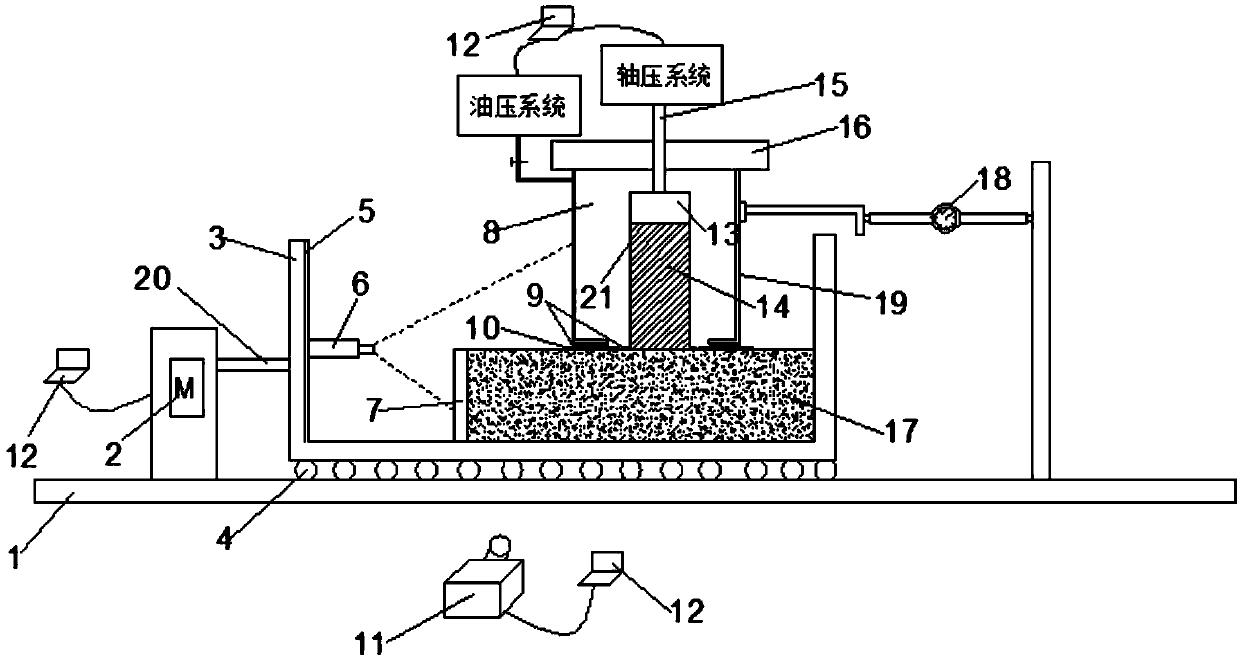
[0050] The invention provides a visual test device for the study of shear properties of soil and structures, such as figure 1 and 2 As shown, including upper shearing system, lower shearing system, horizontal force applying device, pressure control system and data acquisition system;

[0051] Downshear systems include:

[0052] The base 3 is arranged on an optical platform 1, and a liquid drop 4 is arranged between the base 3 and the optical platform 1;

[0053] The shear box 7 is arranged above the base 3 and is used to place the structure to be tested; the shear box 7 is made of plexiglass.

[0054] The upper shear system includes:

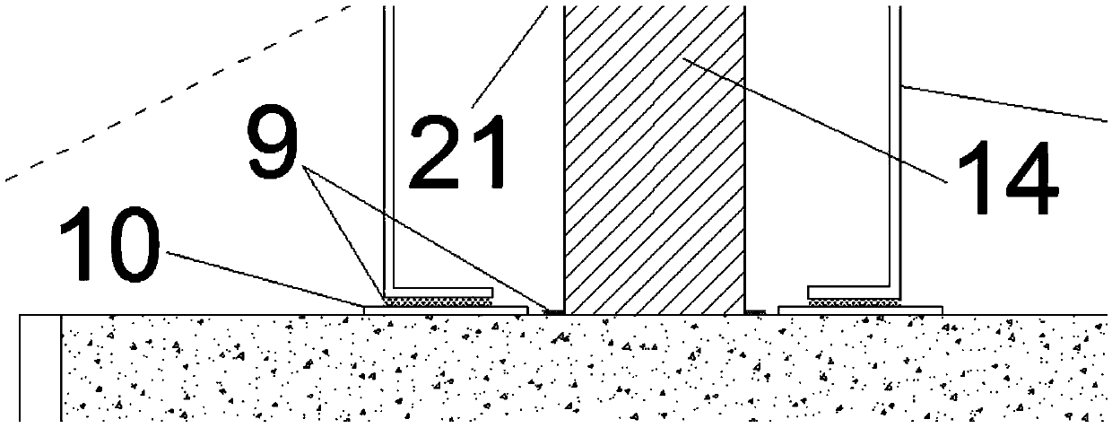
[0055] The glass cylinder 19 is open up and down, and the upper end of the glass cylinder 19 is provided with an upper cover 16 . The glass cylinder 19 is set on the structure to be tested, and the glass plate 10 is set between the glass cylinder 19 and the structure to be tested; the graphene 9 is set between the glass cylinder 19 and the gla...

Embodiment 1

[0082] What embodiment 1 adopts is to carry out the study of the shear characteristic of soil and structure contact surface under the condition of controlling rock-like or concrete-like material 17 confining pressure and axial pressure constant, for the soil-structure contact surface shearing under the change of confining pressure For the study of characteristics, on the basis of Example 1, the implementation of step 5 can be changed. The initial confining pressure of the shearing process is set to 100MPa by the oil pressure system, each increase is 50MPa, and the interval is 120s; the axial pressure is kept constant at 300MPa during the shearing process, and the change of the horizontal displacement is paid close attention to during the test. When the horizontal displacement is observed When the reading in Table 18 is 0.4mm, the test is stopped; after the test, the obtained pictures are analyzed by the computer image processing software PIV, and the changes of the stress and d...

Embodiment 3

[0084] For the research on the shear characteristics of the contact surface between soil and structure under the change of axial pressure, the implementation of step 5 can be changed on the basis of Example 1. The initial axial pressure of the shearing process is set to 100MPa by the hydraulic system, and each increase is 50MPa, with an interval of 120s; the confining pressure is kept constant at 200MPa during the shearing process, and the change of the horizontal displacement is paid close attention to during the test. When the horizontal displacement is observed When the reading in Table 18 is 0.4mm, the test is stopped; after the test, the obtained pictures are analyzed by the computer image processing software PIV, and the changes of the stress and displacement of the contact surface when the soil and the structure are sheared under the change of axial pressure are obtained process.


PUM

PropertyMeasurementUnit
sizeaaaaaaaaaa
thicknessaaaaaaaaaa
diameteraaaaaaaaaa

Abstract

The invention provides a visual testing device and method for soil and structure shearing characteristic research. The visual testing device comprises an upper shearing system, a lower shearing system, a horizontal force applying device and a data acquisition system. The upper shearing system is composed of transparent soil, a glass cylinder, an oil hydraulic system and an axial pressing system. An upper cover is arranged on the upper portion of the glass cylinder, and a loading rod and a loading plate are arranged between the axial pressing system and the transparent soil. The lower shearingsystem is composed of a rock-like or concrete-like material, a shearing box and a base. The horizontal force applying system is composed of a motor, a propelling worm and a horizontal displacement meter. A hand wheel applies horizontal push force to the base through the propelling worm, and liquid beads are arranged between an optical platform and a shearing box. The data acquisition system is composed of a laser, a CCD camera and a computer. By means of the visual testing device and method, the problem that contact surface stress and displacement are not visible during soil and structure shearing failures is solved, and the purpose of visual observation of the contact surface during soil and structure shearing failures is achieved.

Description

technical field [0001] The invention belongs to the field of geotechnical engineering tests, and in particular relates to a visual test device and method for studying the shear properties of soil and structures. Background technique [0002] As one of the important factors for the stability of geotechnical engineering, the interface between soil and structure, its shear mechanical properties have always been the focus of attention in the industry. The easiest and most commonly used method for determining the shear strength on the predetermined shear failure plane during the direct shear test. The equipment structure of the direct shear test is simple, the preparation and installation of the sample are convenient, and the operation is easy to master. It is still widely used by scientific research and engineering units. The thickness of the sample used in the test is small, and the consolidation is fast, which can save the test time. In addition, since the shearing box 7 is ...

Claims


Application Information

Patent Timeline
Patent Type & Authority Applications(China)
IPC IPC(8): G01N3/24G01N3/02G01N3/06
CPCG01N3/02G01N3/068G01N3/24G01N2203/0025G01N2203/0647
Inventor 倪小东徐硕姬良龙
Owner HOHAI UNIV
Why Eureka
Try Eureka