
Composite wood beam and production line thereof

A production line and wood cube technology, applied in layered products, wood layered products, wood processing appliances, etc., can solve the problems of insufficient strength of composite wood cubes, high cost of recycled plastic wrapping, and increased mold cost.

Pending Publication Date: 2018-12-28
石家庄青林机械设备有限公司
View PDF1 Cites 7 Cited by
  • Summary
  • Abstract
  • Description
  • Claims
  • Application Information

AI Technical Summary

Problems solved by technology

[0002] Existing composite wood squares are formed by wrapping a whole piece of wood with plastic or iron sheet. The assembly line generally includes four-sided planing equipment, tractor, double-sided nailing, cutting machine and other equipment. The peripheral package needs to make molds of equal length. Production requires pressing square materials of various lengths and specifications. If matching production requirements, it is necessary to equip molds of various lengths, which greatly increases the cost of the mold.
There are also composite wood squares that use multiple pieces of waste templates to dislocate the joints, such as the invention patent with the application number: CN201711326746.1, which is fixed and connected by horizontal iron nails penetrating the templates, and the surface layer attached to the base core is recycled plastic. The processing methods include: Material preparation, material selection, trimming, stripping, splicing, nailing, fine planing, cladding, and cooling molding. This kind of production line has technical problems such as splicing waste templates out of order, resulting in insufficient strength of composite wood and high packaging costs of recycled plastics.

Method used


Image

  • Composite wood beam and production line thereof
  • Composite wood beam and production line thereof
  • Composite wood beam and production line thereof

Examples


Embodiment Construction

[0050] The following will clearly and completely describe the technical solutions in the embodiments of the present invention with reference to the accompanying drawings in the embodiments of the present invention. Obviously, the described embodiments are only some, not all, embodiments of the present invention. Based on the embodiments of the present invention, all other embodiments obtained by persons of ordinary skill in the art without creative efforts fall within the protection scope of the present invention.

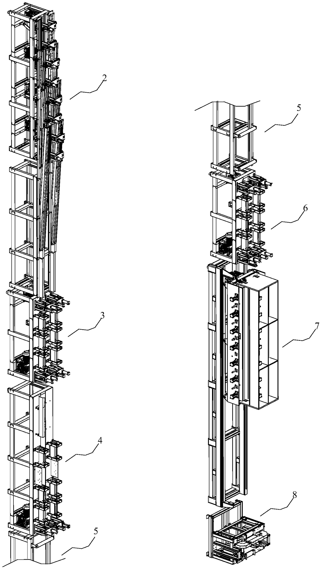
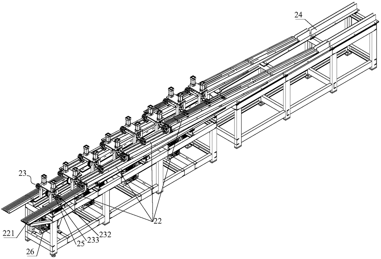
[0051] Such as Figure 1 to Figure 17 As shown, the present invention proposes a kind of composite wood square and production line thereof, comprising:

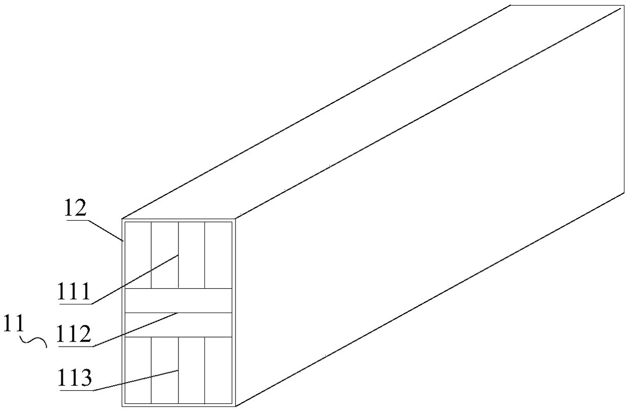
[0052] The wooden cube body 1 is provided with a wrapping layer 12 outside the wooden cube body 1. The wooden cube body 1 includes several closely arranged wooden strip groups 11. The wooden strip groups 11 are composed of several wooden strips arranged in parallel with the same width and height, adjacent to each ...


PUM


Abstract

The invention belongs to the technical field of wood beam production, and discloses a composite wood beam and a production line thereof. The composite wood beam and the production line thereof comprise a wood beam body, and a wrapping layer is arranged outside the wood beam body. The wood beam body comprises a plurality of layers of batten groups closely arranged, the batten groups are composed ofa plurality of battens with same widths and heights in a parallel arrangement mode, and the arrangement directions of the two adjacent batten groups are perpendicular each other. The composite wood beam comprises a feeding device, a first heating and pressing device and a cloth wrapping device, the feeding device comprises a plurality of feeding channels which are arranged up and down and with uniform widths, and the feeding channels converge at the end close to the first heating and pressing device. The feeding channels comprise a plurality of grooves parallel mutually for feeding, the battens form the batten groups through the feeding channels, and the technical problem that an existing batten has low intensity is solved.

Description

technical field [0001] The invention belongs to the technical field of wood cube production, and relates to a composite wood cube and a production line thereof. Background technique [0002] Existing composite wood squares are formed by wrapping a whole piece of wood with plastic or iron sheet. The assembly line generally includes four-sided planing equipment, tractor, double-sided nailing, cutting machine and other equipment. The peripheral package needs to make molds of equal length. Production requires pressing square materials with various lengths and specifications. If the production requirements are matched, it is necessary to be equipped with molds of various lengths, which greatly increases the cost of the mold. There are also composite wood squares that use multiple pieces of waste templates to dislocate the joints, such as the invention patent with the application number: CN201711326746.1, which is fixed and connected by horizontal iron nails penetrating the templa...

Claims


Application Information

Patent Timeline
IPC IPC(8): B27D1/00B27D1/10B27D5/00B27G3/00B32B21/14B32B21/04B32B17/02B32B17/06B32B3/18B32B37/06B32B37/10B32B37/12B32B38/00B32B38/16
CPCB27D1/00B27D1/10B27D5/00B27G3/00B32B3/18B32B5/02B32B21/042B32B21/10B32B21/14B32B37/06B32B37/10B32B37/12B32B38/0004B32B38/164B32B2317/16B32B2262/101
Inventor 程存伟
Owner 石家庄青林机械设备有限公司
Learn More