Railway vehicle bogie dynamic debugging test bed

A technology for dynamic debugging and railway vehicles, applied in the direction of railway vehicle testing, etc., to achieve the effects of authentic test data, low test cost, and high test efficiency

Pending Publication Date: 2018-12-28
SOUTHWEST JIAOTONG UNIV
View PDF11 Cites 6 Cited by
  • Summary
  • Abstract
  • Description
  • Claims
  • Application Information

AI Technical Summary

Problems solved by technology

[0006] The purpose of the present invention is to provide a dynamic debugging test bench for railway vehicle bogies, aiming to solve the problem of completing bogie axle fatigue tests, braking tests, adhesion tests, and dynamic performance tests under various environmental conditions. At the same time, wheel set derailment can also be completed. and tread wear test and other related tests

Method used


Image

  • Railway vehicle bogie dynamic debugging test bed
  • Railway vehicle bogie dynamic debugging test bed
  • Railway vehicle bogie dynamic debugging test bed

Examples


Embodiment 1

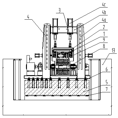
[0029] Figures 1~4 It is shown that a specific embodiment of the present invention is: a railway vehicle bogie dynamic debugging test bench, which at least includes a steel frame 4 , and also includes a force applying frame 2 and an actuator 3 fixed on the steel frame 4 . , base block 5, guide rail 6 laid on base block 5, rubber spring 7 for vibration isolation of base block 5, transmission device 8, environmental simulation device 9, thin oil station 10, track 11, fan 12, foundation 13 and The cross beam 14 is reinforced, the guide rail 6 is installed on the upper surface of the base block 5, the rubber spring 7 is arranged under the base block 5, the steel frame 4 and the transmission device 8 are slidably connected on the guide rail 6, and the transmission device 8 is located in the steel frame. Inside the frame 4, an environment simulation device 9 is arranged on the transmission device 8, the force application frame 2 is arranged in the environment simulation device 9, a...

Embodiment 2

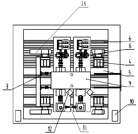
[0045] like Figure 1-4 As shown in the test bench for dynamic debugging of a railway vehicle bogie, the specific structure of the transmission device 8 includes: a motor 8a, a first coupling 8b1, a second coupling 8b2, a third coupling 8b3, a gear Box 8c, pie torque sensor 8d, diaphragm coupling 8e, bearing seat 8f, roller 8g, steering gear 8h and universal joint 8i, the drive end of the motor 8a communicates with the gear box through the first coupling 8b1 8c is connected at one end, the other end of the gear box 8c is connected with one end of the pie torque sensor 8d through the second coupling 8b2, the roller 8g is supported by the bearing seat 8f, and one end of the roller 8g is connected with the pie through the diaphragm coupling 8e. The other end of the torque sensor 8d is connected to the other end, and the other end of the roller 8g is connected to the steering gear 8h through the third coupling 8b3. There are two transmission devices 8. 8i is connected, and the th...

Embodiment 3

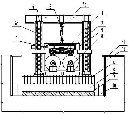
[0054] according to Figures 1~4 As shown in the test bench for dynamic debugging of a railway vehicle bogie, the foundation 13 is a rectangular structure concave on the ground and the upper end is open, the foundation block 5 is arranged on the lower bottom surface of the rectangular structure of the foundation 13, and the track 11 is detachably connected to the foundation 13 and is horizontal with the top of the transmission device 8 . The thin oil station 10 is arranged on the lower bottom surface of the rectangular structure of the foundation 13 .

[0055] Preferably, the bogie 1 , the rollers 8d in the transmission device 8 and the force applying frame 2 are all located in the inner cavity of the environment simulation device 9 .

[0056] Preferably, the steel frame 4 includes: a column 4a, a beam 4b and a longitudinal beam 4c, the column 4a is vertically slidably connected to the guide rail 6, the beam 4b is detachably connected to the column 4a, and the longitudinal bea...


PUM


Abstract

The invention relates to the field of performing dynamic debugging testing on the railway locomotive vehicle bogie, and in particular relates to a railway vehicle bogie dynamic debugging test bed. Through the arrangement of a bogie for test, a force application frame for restraining the bogie, actuators, a steel frame for fixing the actuators, a foundation block, a guide rail laid on the foundation block, rubber springs for the vibration isolation of the foundation block, transmission devices, an environmental simulation device, a pair of thin oil stations, a rail, fans, a foundation, and a reinforced beam, the braking test, the adhesion test, the dynamic performance and tread abrasion test of the bogie can be performed.

Description

technical field [0001] The invention belongs to the technical field of dynamic debugging and testing of railway vehicle bogies, in particular to a dynamic debugging test bench for railway vehicle bogies. Background technique [0002] With the development of high-speed railways and the deterioration of the service environment of various components in the operation of China's EMUs for more than ten years, the structural strength problems exposed to bogies, axles and car bodies have gradually increased. The environment is very different, so it is necessary to carry out the fatigue test of the bogie axle under various environmental conditions. [0003] With the increase of train running mileage, the bogie and rails have different degrees of wear and tear. The worn vehicle condition has more and more serious vibration impact on the bogie components, which greatly affects the life of the vehicle components. At the same time, with the opening of China's Xicheng high-speed railway,...

Claims


Application Information

Patent Timeline
Patent Type & Authority Applications(China)
IPC IPC(8): G01M17/08
CPCG01M17/08
Inventor 宋烨邬平波曾京戴焕云刘潮涛贾璐
Owner SOUTHWEST JIAOTONG UNIV
Why Eureka
Try Eureka