Intelligent dynamic pressure bearing

A technology of dynamic pressure bearings and bearings, which is applied in the direction of bearings, sliding contact bearings, and rotating bearings. It can solve problems such as whirl and dry friction, interference with stable operation of the system, and equipment speed reduction, so as to avoid direct contact. Effects of friction, weight reduction of liquid supply and cooling system, and small amount of liquid supply

Active Publication Date: 2019-01-01
TSINGHUA UNIV
View PDF11 Cites 2 Cited by
  • Summary
  • Abstract
  • Description
  • Claims
  • Application Information

AI Technical Summary

Problems solved by technology

However, the gas dynamic pressure bearing needs the rotor (that is, the rotating shaft) speed to reach a certain limit to generate a dynamic pressure gas film. Usually, the rotor takes off at a linear speed greater than 20m / s. During the rotor start and stop phase, the journal is in direct contact with the bearing, resulting in wear; In addition, the stability of the bearing is relatively poor during operation, and instability phenomena such as eddy motion and dry friction are prone to occur. After the instability, the equipment has to reduce the speed or even shut down in an emergency, which seriously interferes with the stable operation of the system.
[0005] In order to improve the stability and reliability of gas dynamic pressure bearings, support structures such as foils, compression springs, wire mesh, bulges, and foil-wire mesh hybrids have been proposed, which have improved the performance of the bearing to a certain extent. However, The above structure does not essentially overcome the shortcomings of gas lubrication, and the effect is limited

Method used


Image

  • Intelligent dynamic pressure bearing
  • Intelligent dynamic pressure bearing
  • Intelligent dynamic pressure bearing

Examples


Embodiment Construction

[0044] Exemplary embodiments of the present invention are described below with reference to the accompanying drawings. It should be understood that these specific descriptions are only used to teach those skilled in the art how to implement the present invention, but are not intended to exhaust all possible ways of the present invention, nor are they intended to limit the scope of the present invention.

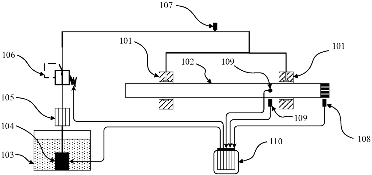
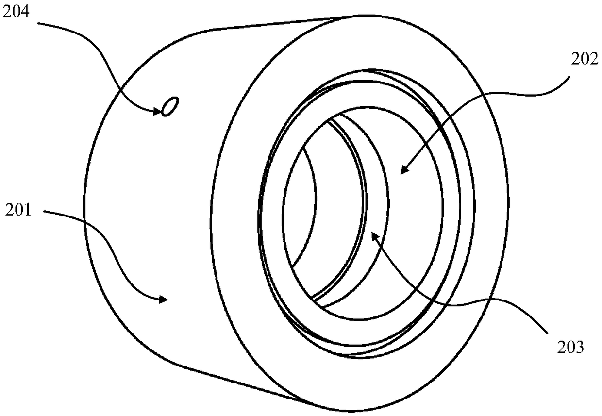
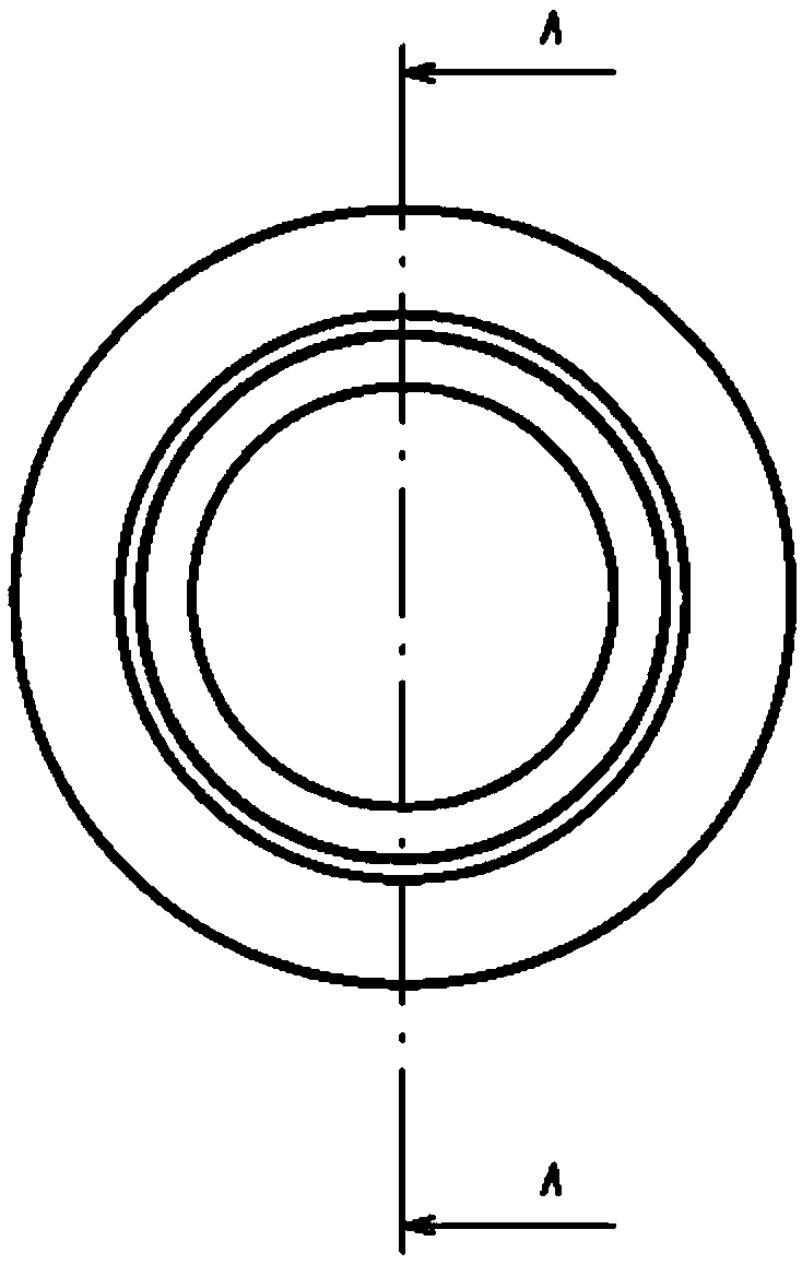
[0045] Such as figure 1 , figure 2 , Figure 3A and Figure 3B As shown, an embodiment of the present invention provides an intelligent dynamic pressure bearing, which includes a bearing body 101 , a liquid supply system and a control system.

[0046] The bearing body 101 includes a bearing seat 201 and a bearing shell 202 . A liquid storage groove (for example, an oil groove) 203 extending in the circumferential direction is formed on the inner peripheral surface of the bearing bush 202 . The bearing housing 201 and the bearing bush 202 are formed with a liquid supply ...


PUM


Abstract

The invention provides an intelligent dynamic pressure bearing. A control system of the bearing comprises a sensor and a control unit, wherein the sensor is used for monitoring at least one operationparameter of a bearing body or a rotor supported by the bearing body and sending the monitored parameter to the control unit; the at least one operation parameter is used for at least characterizing arotary speed of the rotor or at least characterizing an operation load of the bearing body or the rotor. When the rotary speed of the rotor is less than a pre-set speed or when the operation load ofthe bearing body or the rotor is greater than a pre-set load, lubrication liquid is supplied to the bearing body through a liquid supply system, so that the intelligent dynamic pressure bearing is used as a liquid dynamic pressure bearing to work. When the rotary speed of the rotor is greater than or equal to the pre-set speed and when the operation load of the bearing body or the rotor is less than or equal to the pre-set load, the liquid supply system stops supplying the lubrication liquid to the bearing body, so that the intelligent dynamic pressure bearing is used as a gas dynamic pressurebearing to work. The intelligent dynamic pressure bearing has the advantages of the gas dynamic pressure bearing and the liquid dynamic pressure bearing.

Description

technical field [0001] The invention relates to the technical field of bearings, in particular to an intelligent dynamic pressure bearing. Background technique [0002] Dynamic pressure bearing is a kind of sliding bearing with dynamic pressure fluid as lubricating medium, which is mainly divided into hydrodynamic pressure bearing and gas dynamic pressure bearing. Due to the small frictional resistance, strong load carrying capacity and simple structure, dynamic pressure bearings are widely used in industry. [0003] Hydrodynamic bearings use liquid (such as lubricating oil) as a lubricant, and have a strong load-carrying capacity. However, when the linear velocity of the journal increases, the friction loss of the bearing increases gradually, which increases the power consumption and makes the problem of heat dissipation of the lubricant very prominent. At present, the journal linear velocity of a typical hydrodynamic bearing is usually not more than 60m / s, which restrict...

Claims


Application Information

Patent Timeline
Patent Type & Authority Applications(China)
IPC IPC(8): F16C17/24
CPCF16C17/243F16C17/246F16C17/02F16C17/024F16C33/1005F16C33/1025F16C33/1045F16C33/6674F16C2326/43F16C2360/23
Inventor 张卫锋顾永鹏冯光烁任革学梁峰周明
Owner TSINGHUA UNIV
Why Eureka
Try Eureka