Vision-based spraying drone

A plant protection UAV and visual technology, applied in the field of agricultural plant protection, can solve the problems of large volume, great influence of barometric altimeter, complicated use, etc., to reduce the measurement accuracy, facilitate the establishment process, and improve the calculation speed.

Pending Publication Date: 2019-01-04
NORTH CHINA UNIV OF WATER RESOURCES & ELECTRIC POWER
View PDF0 Cites 3 Cited by
  • Summary
  • Abstract
  • Description
  • Claims
  • Application Information

AI Technical Summary

Problems solved by technology

Due to the instability of GPS received data, it is greatly affected by external interference, such as the height of surrounding buildings and terrain factors. The error is small, and the stability is still unsatisfactory, and its cost is high, the volume is large, and it is not suitable for small agricultural drones to fly at a certain height
The measurement accuracy of the radio altimeter can meet the flight requirements, but it is relatively complicated to use, and antennas need to be added to both the UAV and the ground station, and its cost is relatively high, so it is not suitable for small agricultural UAVs
The pressure sensor overcomes many shortcomings of GPS, and is optimized in terms of accuracy, cost, and volume. At the same time, it has the advantage of being easy to use, but it is easily affected by weather changes, especially when flying at low altitudes for micro-sized agricultural drones. The complex ground effect caused by the canopy structure of farmland crops has a great impact on the barometric altimeter, and the flight stability is difficult to guarantee

Method used


Image

  • Vision-based spraying drone
  • Vision-based spraying drone
  • Vision-based spraying drone

Examples


Embodiment Construction

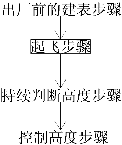
[0032] Such as Figure 1 to Figure 6 As shown, the vision-based plant protection drone of the present invention comprises a disc-shaped housing 1 arranged horizontally, and the housing 1 is uniformly hinged with some cantilevers 2 in its circumferential direction, and the other end of the cantilever 2 is a free end; The cantilever 2 is arranged along the radial direction of the housing 1 and the free end of each cantilever 2 is higher than the hinged end;

[0033]The front and rear sides of the housing 1 are respectively provided with a front landing gear 3 and a rear landing gear 4 downwards, the upper surface of the housing 1 is connected with a push rod 5 upwards, and the top of the push rod 5 is provided with a GPS module 6; There is a flight controller and a storage battery connected to the flight controller and providing power to the flight controller. The free ends of each cantilever 2 are provided with motors 7, and the output shafts of the motors 7 are connected upwar...


PUM


Abstract

The invention discloses a vision-based spraying drone. The vision-based spraying drone comprises a shell, a plurality of cantilevers are uniformly hinged to the shell, a front undercarriage and a rearundercarriage are downwardly arranged on a front side and a rear side of the shell respectively, a top pole is upwardly connected onto an upper surface of the shell, a GPS (global positioning system)module is arranged at the top end of the top pole, a flight control unit and a storage battery are arranged inside the shell, motors are respectively arranged at free ends of the cantilevers, propellers are upwardly connected with output shafts of the motors, a suspension frame is downwardly connected onto the position, between the front undercarriage and the rear undercarriage, of the shell, a laser transmitter is arranged at the left end of the suspension frame, a camera is arranged at the right end of the suspension frame, a camera lens optical axis of the camera intersects with a straightline of laser light emitted by the laser transmitter, an included angle theta between the camera lens optical axis of the camera and a horizontal plane ranges from 50 degrees to 75 degrees, and a miniPC (mini personal computer) is arranged in a middle portion of the suspension frame. The vision-based spraying drone is simple in structure, facula caused by the laser transmitter is enabled to locate in a vertical center line of a photo image shot by the camera, less image deformation is realized, and a good foundation is provided for image processing.

Description

technical field [0001] The invention relates to the field of agricultural plant protection, in particular to the technology of spraying pesticides by a plant protection drone. Background technique [0002] With the shortage of rural labor force in our country, the rapid increase of labor costs and the rapid development of specialized unified prevention and control work, the society requires large and medium-sized plant protection machinery with high operating efficiency, wide application range, water saving, chemical saving and environmental protection, and less labor. And the demand for agricultural aviation plant protection machinery is becoming more and more urgent. Plant protection UAVs have the advantages of good mobility, high operating efficiency, small amount of spraying liquid per unit area, no need for special take-off and landing airports, remote control operations, reduced chances of personal injury, and improved effective utilization of pesticides. It adapts to...

Claims


Application Information

Patent Timeline
Patent Type & Authority Applications(China)
IPC IPC(8): B64C27/08B64D47/08G06K9/00
CPCB64C27/08B64D47/08G06V20/10B64U2101/30B64U50/19B64U10/10
Inventor 马子领张瑞珠吴高峰
Owner NORTH CHINA UNIV OF WATER RESOURCES & ELECTRIC POWER
Why Eureka
Try Eureka