Workpiece feeding device and method

A technology for retrieving devices and workpieces, applied in conveyor control devices, metal processing, manufacturing tools, etc., can solve problems such as unrecognizable workpiece status, achieve the effects of reducing manual workload, ensuring continuity, and facilitating management

Pending Publication Date: 2019-01-04
SUZHOU RS TECH
View PDF5 Cites 43 Cited by
  • Summary
  • Abstract
  • Description
  • Claims
  • Application Information

AI Technical Summary

Problems solved by technology

[0005] Therefore, the technical problem to be solved by the present invention is to overcome the defect that the state of the workpiece cannot be identified d

Method used


Image

  • Workpiece feeding device and method
  • Workpiece feeding device and method
  • Workpiece feeding device and method

Examples


Embodiment 1

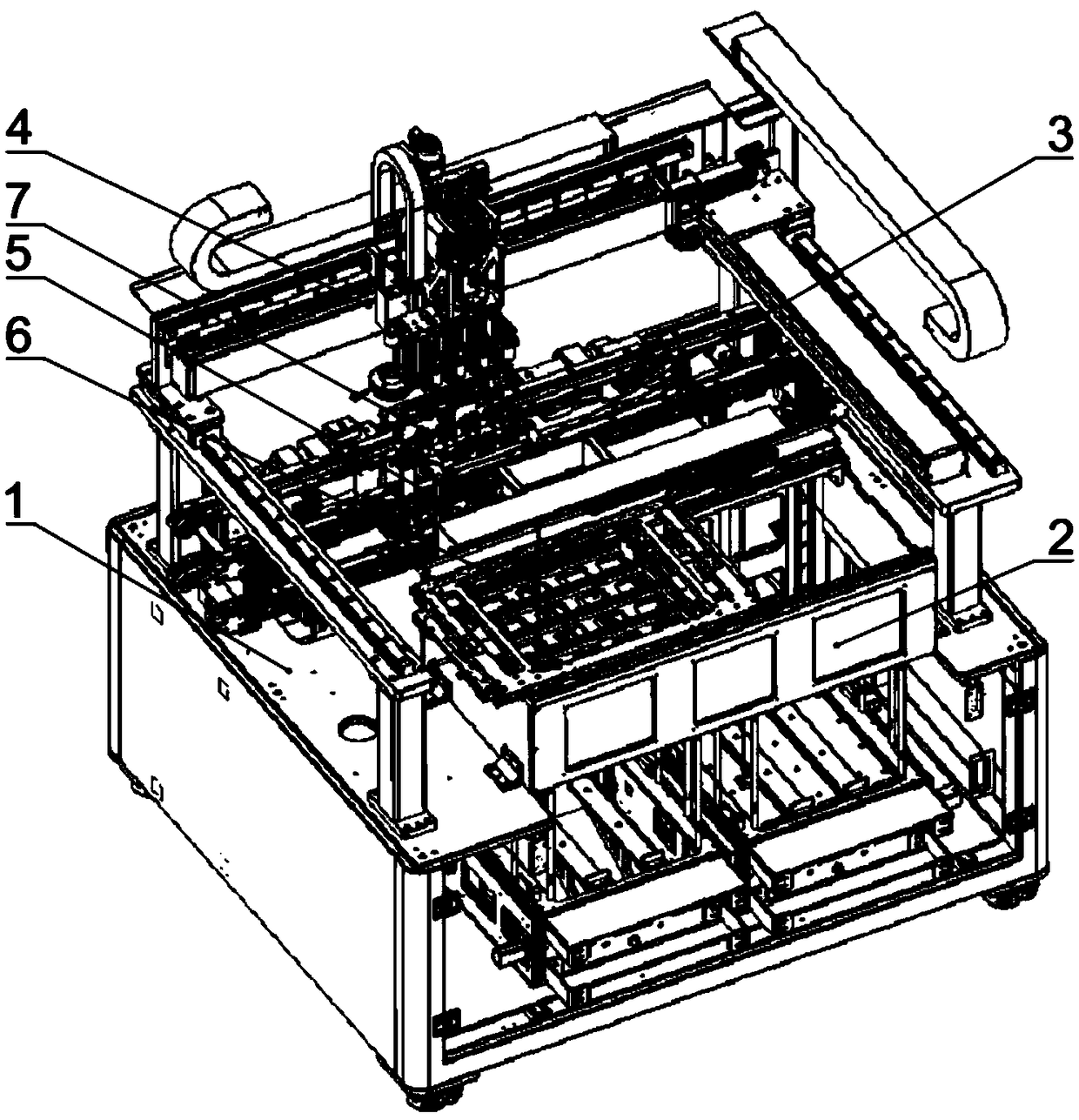
[0077] This embodiment provides a workpiece feeding device, the structure of which is as follows: figure 1 and Figure 12 As shown, it includes a workbench 1, a feeding mechanism 2, a transmission line mechanism 3, a workpiece handling mechanism 4 and a screening mechanism 5. The feeding mechanism 2 is provided with a feeding location 6 , and the transmission line mechanism 3 is provided with an installation location 7 . The workpiece transport mechanism 4 clamps the workpiece 8 from the feeding position 6 , and after being detected and screened by the screening mechanism 5 , moves and installs the qualified workpiece 8 to the target carrier 33 at the installation position 7 .

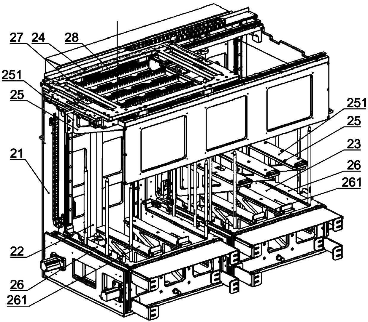
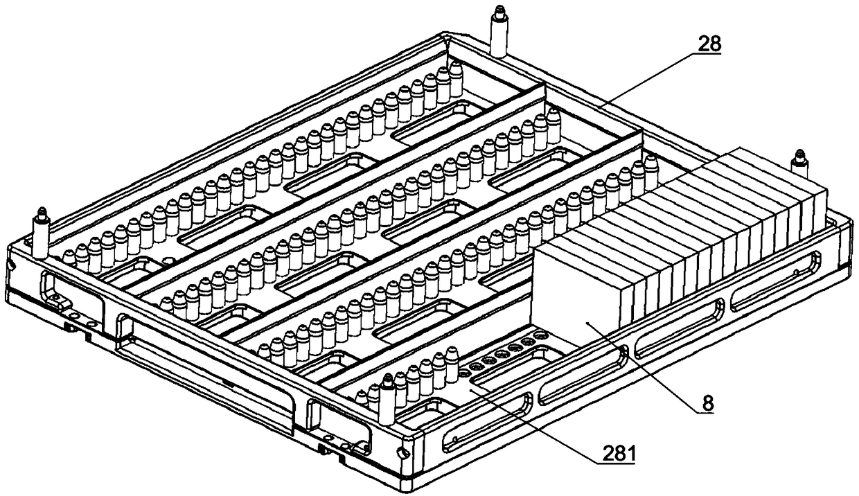
[0078] Such as figure 1 and figure 2 As shown, the feeding mechanism 2 in this embodiment adopts a clip-type feeding method for feeding, and it has a feeding area 22 for carrying the tray 28 and a return area 23 for recovering the tray 28 . Both the feeding area 22 and the returning area 23 are pr...

Embodiment 2

[0109] This implementation provides a workpiece feeding method, using the workpiece feeding device in Embodiment 1 to perform the following steps:

[0110] The detection mechanism on the reclaiming device detects the material tray at the feeding position, and takes pictures of the workpiece through the upper camera to obtain the position of the workpiece in the material tray;

[0111] The clamping unit determines the clamping position according to the detection result;

[0112] The moving device drives the reclaimer to move above the screening mechanism. The shape detection unit detects the shape of the workpiece. The reclaimer adjusts the clamping state of the workpiece according to the detection results. If the workpiece is qualified, it will maintain the clamping state. If the workpiece is unqualified, it will Release the grip on the workpiece and throw the workpiece into the waste box;

[0113] The detection mechanism on the reclaimer detects the carrier on the installati...


PUM


Abstract

The invention provides a workpiece feeding device. The workpiece feeding device comprises a working platform, a supplying mechanism, a conveying line mechanism, a workpiece carrying mechanism and a screening mechanism, wherein a supplying position is arranged on the supplying mechanism; a mounting position is arranged on the conveying line mechanism. According to the device, the workpiece carryingmechanism is capable of clamping a workpiece from the supplying position; the workpiece subjected to detecting and screening of the screening mechanism moves and then is mounted to a target carrier at the mounting position; the supplying mechanism and the workpiece carrying mechanism realize automatic workpiece supplying and feeding and mounting; the workpiece can be detected through the screening mechanism in the carrying process, so that the qualification rate of the workpiece is ensured; the workpiece is carried through the conveying line mechanism utilizing the carrier, and thus the flow-line type processing work is realized. The invention also provides a workpiece feeding method. With the adoption of the device and the method, the workpiece is automatically fed and detected, and thusthe convenience of production management is ensured.

Description

technical field [0001] The invention relates to the technical field of automatic assembly, in particular to a workpiece feeding device and a workpiece feeding method. Background technique [0002] Automation technology is widely used in industry, agriculture, military, scientific research, transportation, commerce, medical care, services and households. The use of automation technology can not only liberate people from heavy physical labor, part of mental work, and harsh and dangerous working environments, but also expand human organ functions, greatly improve labor productivity, and enhance human ability to understand and transform the world. . [0003] In the electronic equipment assembly process, it is often necessary to clamp the workpiece at a certain station, move and rotate in multiple directions, and change its position. Realize the cooperation between the workpiece and the assembly carrier. These actions need to be completed by automated processing equipment such...

Claims


Application Information

Patent Timeline
IPC IPC(8): B65G47/90B65G43/08B23P19/00
CPCB65G43/08B65G47/901B23P19/001B65G2203/041
Inventor 吴加富缪磊高冬青郑俊杰冯小平郑文坛
Owner SUZHOU RS TECH
Why Eureka
Try Eureka