A superjunction device and a method for manufacturing the same

A superjunction device and charge technology, which is applied in the field of semiconductor integrated circuit manufacturing, can solve the problems of device performance and reliability, limited coverage of metal contact holes, small size and other problems

Active Publication Date: 2019-01-04
SHENZHEN SANRISE TECH CO LTD
View PDF16 Cites 1 Cited by
  • Summary
  • Abstract
  • Description
  • Claims
  • Application Information

AI Technical Summary

Problems solved by technology

[0004] For ease of design, or in order to reduce the number of photolithography, in the case of using the thick field oxide film as self-alignment and performing source region ion implantation, at least part of the P-type ring in the transition region needs to be covered by the thick field oxide film , so the aspect ratio of the contact hole on the region covered by the thick oxide film will be greater than the minimum aspect ratio of the contact hole in the charge flow region, wherein the contact hole in the charge flow region only needs to pass through the interlayer film, and the transition region The contact hole on the area covered by the thick oxide film needs to pass through the interlayer film and the thick oxide film at the same time, so the aspect ratio of the contact hole on the area covered by the thick oxide film will be greater than that of the charge flow area. The minimum aspect ratio of the contact hole; and in the existing technology, when the metal deposition is the manufacturing process of Ti, TiN and ALCu, Ti, TiN and ALSiCu, the coverage of the metal to the metal contact hole is limited, and the height and width If the hole is higher than 0.5, metal pinholes will appear during metal filling, causing performance and reliability problems of the device
[0005] On the other hand, when the step (Pitch) of the super junction MOSFET is not shortened, the size of the N-type drift region between the P-type pillars is continuously reduced, so the implanted region of the P-type well is greater than or equal to the P-type In the case of the width of the pillar, the size of the effective N-type region at the channel surface is getting smaller and smaller, which seriously affects the specific on-resistance of the device

Method used


Image

  • A superjunction device and a method for manufacturing the same
  • A superjunction device and a method for manufacturing the same
  • A superjunction device and a method for manufacturing the same

Examples


Embodiment Construction

[0074] The super junction device of the embodiment of the present invention:

[0075] Such as Figure 6 As shown, it is a top view of the formation area of ​​the source 7a7a and the gate 7b7b formed by the front metal layer of the superjunction device of the embodiment of the present invention; Figure 1 to Figure 5 as well as Figure 7 to Figure 10 For explanation, the details are as follows:

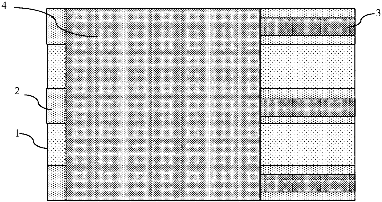
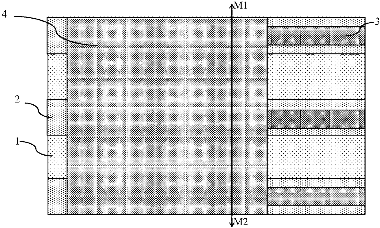
[0076] The super-junction device in the embodiment of the present invention is described by taking the super-junction MOSFET as an example. The middle region of the super-junction device in the embodiment of the present invention is the charge flow region, the terminal region surrounds the outer periphery of the charge flow region, and the transition region is located in the charge flow region. region and the termination region; the superjunction device according to the embodiment of the present invention includes:

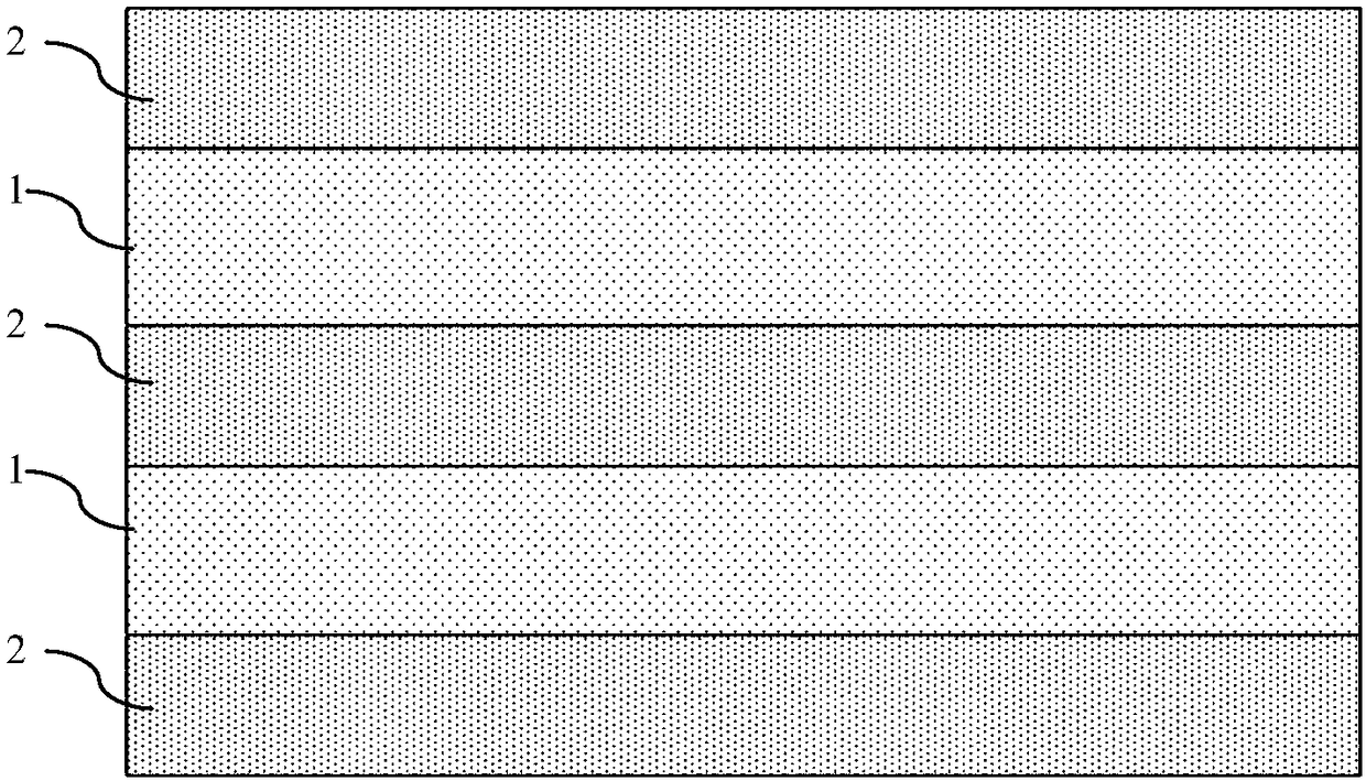
[0077] N-type epitaxial layer 1, the N-type epitaxial layer 1 is d...


PUM


Abstract

A superjunction device is disclosed. A protective epoxidation film surrounding the periphery of the charge flow region is provided, the aspect ratio of the contact hole in the transition region is greater than or equal to the aspect ratio of the contact hole in the charge flow region, and the tungsten plug process is used to fill the contact holes with different aspect ratios reliably at the sametime. The width of the P-type well is smaller than the width of the P-type column, and a slowly varying junction diode is formed between the P-type well and the N-type region. The invention also discloses a manufacturing method of a superjunction device. The invention can reliably fill the contact hole in the transition region when the height-to-width ratio is high, at that same time, the anti-avalanche breakdown ability of the device is not affect by the contact hole process of the transition region, and the influence of the P-type well on the width of the N-type region at the position of thechannel region is reduce, so that the on resistance of the device is reduced; and the nonlinearity of the output capacitance of the device is improved and the EMI problem in device application is improved.

Description

technical field [0001] The invention relates to the field of manufacturing semiconductor integrated circuits, in particular to a super junction device; the invention also relates to a method for manufacturing the super junction device. Background technique [0002] In existing superjunction devices, there are alternately arranged P-type columns and N-type columns in the charge flow region. Taking strip-shaped P-N columns that are alternately arranged P-type columns and N-type columns as an example, each N There is a polysilicon gate above the pillar, which can partially cover the surrounding P pillars or not. There is a P-type well (PWell) above each P-pillar, and there is an N+ source region in the P-type well. There is a contact hole, the source metal is connected to the source region through the contact hole, the source metal is connected to the P region, that is, the P-type well, through a high-concentration P+ contact region, and the source metal is the front metal laye...

Claims


Application Information

Patent Timeline
Patent Type & Authority Applications(China)
IPC IPC(8): H01L29/06H01L21/337H01L29/808
CPCH01L29/0634H01L29/66893H01L29/808
Inventor 肖胜安曾大杰
Owner SHENZHEN SANRISE TECH CO LTD
Why Eureka
Try Eureka