Method for generating free-form surface turning tool path through control point drive projection

A technology of projection generation and turning tools, which is applied in the field of ultra-precision machining and complex parts manufacturing, and can solve problems such as machining instability and reduced efficiency of fast tool machining methods

Active Publication Date: 2019-01-08
TIANJIN UNIV
View PDF9 Cites 16 Cited by
  • Summary
  • Abstract
  • Description
  • Claims
  • Application Information

AI Technical Summary

Problems solved by technology

For slow slide servo machining, this method will introduce machining instability; for fast tool servo machining, since the tool only has excellent dynamic response ability in the Z direction, the dynamic response ability of the X axis is affe

Method used


Image

  • Method for generating free-form surface turning tool path through control point drive projection
  • Method for generating free-form surface turning tool path through control point drive projection
  • Method for generating free-form surface turning tool path through control point drive projection

Examples


Embodiment 1

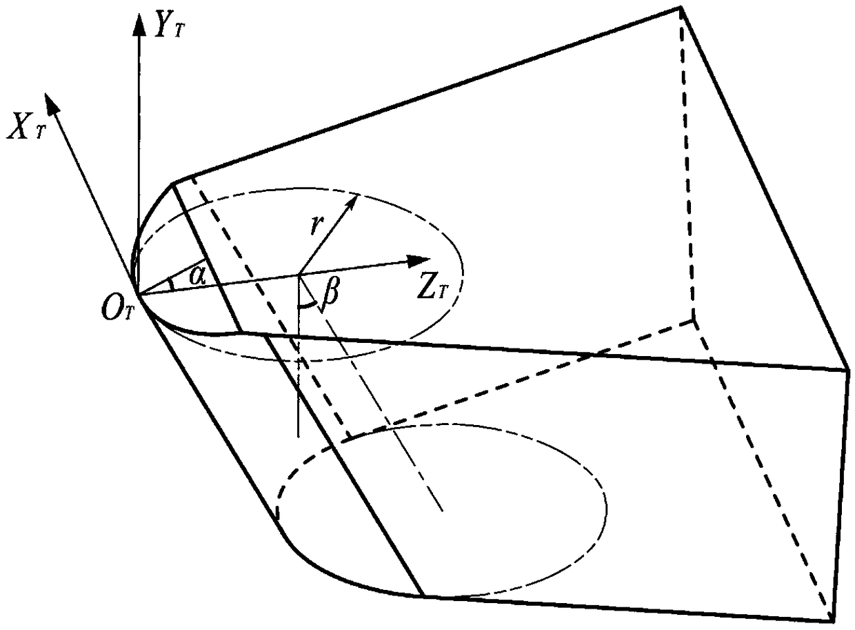
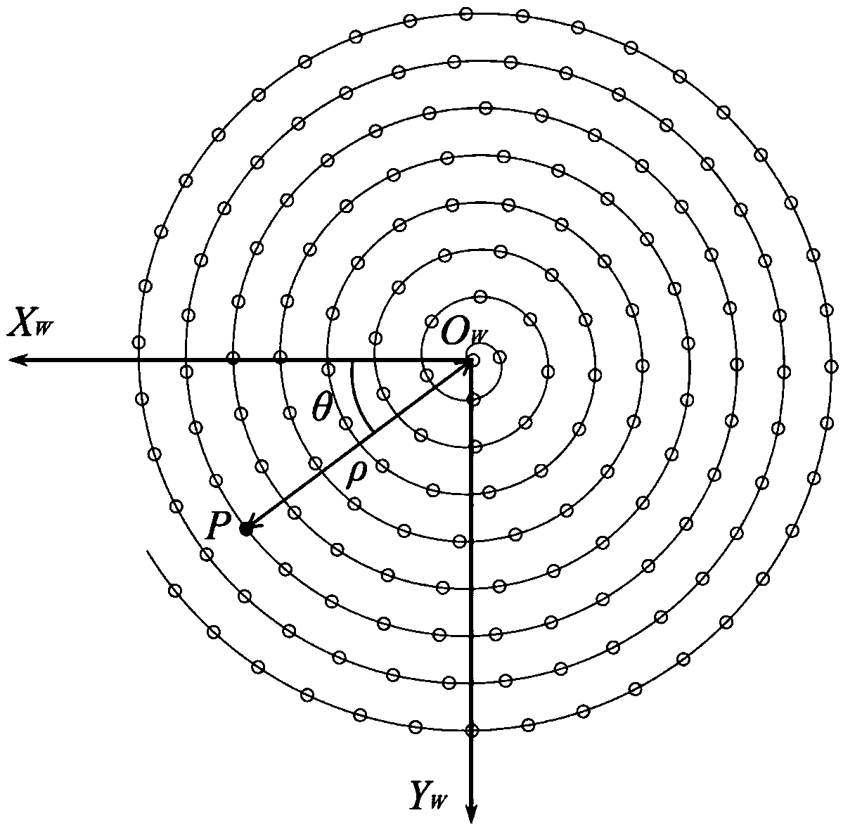
[0058] Taking the free-form surface z=0.1×sin(10x)cos(10y) as an example, use a cylindrical diamond turning tool with rake angle α=-10°, cylinder inclination angle β=20°, and cylinder radius r=0.3mm to process the free-form surface , the pitch of the equidistant helix is ​​set to 0.25mm. The corresponding relationship between the tool control point X coordinate and Z coordinate and the rotation angle θ generated according to the tool path planning method proposed by the present invention is as follows: Figure 4 As shown in the figure, the dotted line in the figure represents the X coordinate of the tool control point, and the solid line represents the Z coordinate. It can be seen from the figure that the X coordinate and θ are in a linear relationship, indicating that when the C axis of the machine tool rotates at a constant angular speed, the tool in the X axis direction is The constant speed moves from the positive direction of the X-axis to the origin without reciprocating...


PUM


Abstract

The invention relates to a method for generating a free-form surface turning tool path through a control point drive projection. The method comprises the steps that a plane perpendicular to the Z axisof a workpiece coordinate system is built at the position zd away from the top of the to-be-processed free-form surface in the workpiece coordinate system, an equidistant spiral line is generated inthe plane and discretized, discretized points are converted into a cylindrical coordinate system (rho, theta, zd), the to-be-processed free-form surface is rotated by the angle theta around the Z axis, the smallest distance delta between each point of the tool edge curve on the equidistant spiral line and the rotated to-be-processed free-form surface is calculated, and therefore the coordinate (rho, 0, zd-delta) of the tool control point is obtained, wherein a tool is a cylindrical turning tool. The projection driving track of the tool control point is preferentially generated, and stability of feeding movement of the tool in the X direction is ensured. By means of the method, a universal model of cylindrical diamond turning tools rather than only zero degree front angle tools is built, and the defects of traditional tool path design methods are overcome.

Description

technical field [0001] The invention belongs to the technical field of ultra-precision machining and complex parts manufacturing, and relates to a method for generating a free-form surface turning tool path through control point-driven projection. Background technique [0002] At present, in the fields of astronomy, communication, microelectronics, and aerospace, with the rapid development of optoelectronic communication technology, higher requirements are put forward for the performance, imaging quality and structure of the optical system. Traditional optical systems need to use multiple optical components to meet the requirements of optical performance and imaging quality, which increases the size of the optical system and the difficulty of assembly and debugging. Compared with traditional rotationally symmetrical optical surfaces, optical free-form surfaces have a great degree of design freedom. Using one or a few free-form optical components can replace multiple spherica...

Claims


Application Information

Patent Timeline
IPC IPC(8): B23B1/00
CPCB23B1/00
Inventor 闫广鹏游开元房丰洲
Owner TIANJIN UNIV
Why Eureka
Try Eureka