
A heat dissipation device for a temperature control system of a PCR detector

A technology of temperature control system and heat dissipation device, which is applied in biochemical cleaning devices, enzymology/microbiology devices, bioreactors/fermenters for specific purposes, etc., can solve the problems of occupying instrument space and disadvantageous instrument miniaturization. , to achieve the effect of high heat dissipation efficiency, rapid and effective heat dissipation, and reduced space occupied

Pending Publication Date: 2019-01-08
HEFEI INSTITUTES OF PHYSICAL SCIENCE - CHINESE ACAD OF SCI +1
View PDF0 Cites 2 Cited by
  • Summary
  • Abstract
  • Description
  • Claims
  • Application Information

AI Technical Summary

Problems solved by technology

Due to its small size and convenience, the miniaturized and portable PCR rapid detection device has a strong limitation on the heat dissipation space. However, the existing instruments are all made of aluminum or copper radiators and cooling fans for heat dissipation, and the radiators and the size of the cooling fan directly affect the heat dissipation efficiency. Therefore, under the condition of satisfying the performance of the instrument, the heat sink and the cooling fan occupy a large proportion of the space of the instrument.

Method used


Image

  • A heat dissipation device for a temperature control system of a PCR detector
  • A heat dissipation device for a temperature control system of a PCR detector

Examples


Embodiment example 1

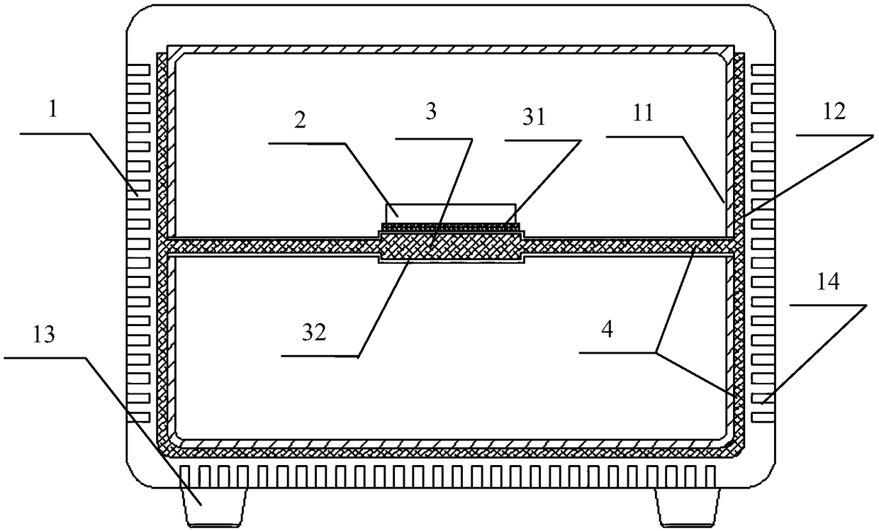
[0022] Implementation Case 1: If figure 1 As shown, a heat dissipation device for a temperature control system of a PCR detector includes a temperature control system 2 , a heat conduction mechanism 3 and a heat dissipation chassis 1 .

[0023] The temperature control system 2 is the temperature control system and structure required for the operation of the PCR detector, and mainly includes heating and cooling devices (such as semiconductor cooling chips) and fixed structures.

[0024] The heat conduction mechanism 3 includes a heat conduction metal layer 32 , a heat conduction pipe 33 , a heat conduction liquid 4 , etc., and the heat conduction mechanism 3 transfers and dissipates heat to ensure the normal operation of the temperature control system 2 . The heat-conducting metal layer 32 is closely attached to the heat-generating and cooling device of the temperature control system 2 that needs to be dissipated through a heat-conducting medium 31 such as graphite sheet or hea...

Embodiment example 2

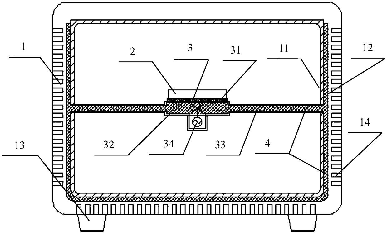
[0028] Implementation Case 2: If figure 2 As shown, adding a micropump 34 on the basis of the implementation case 1 according to actual needs can speed up the circulation speed of the heat transfer liquid, thereby accelerating heat dissipation and improving heat dissipation efficiency. Specifically, a device for cooling the temperature control system of a PCR detector includes a temperature control system 2 , a heat conduction mechanism 3 and a cooling case 1 . A PCR detector that meets higher requirements for temperature control and cooling systems.

[0029] The temperature control system 2 is the temperature control system and structure required for the operation of the PCR detector, and mainly includes heating and cooling devices (such as semiconductor cooling chips) and fixed structures.

[0030] The heat conduction mechanism 3 includes a heat conduction metal layer 32 , a heat conduction pipe 33 , a micropump 34 and a heat conduction liquid 4 , etc. The heat conduction ...


PUM


Abstract

The invention relates to a heat dissipation device for a temperature control system of a PCR detector, which comprises a temperature control system, a heat conduction mechanism and a heat dissipationchassis. Temperature control system refers to the system and structure of temperature control required by PCR detector when it is running. The heat conduction mechanism comprises a heat conduction metal layer, a heat conduction pipe and a heat conduction liquid; The heat-conducting metal layer is closely connected with the heating and refrigerating devices in the temperature control system which need to dissipate heat through the heat-conducting medium. The heat-conducting metal layer contains a cavity filled with a heat-conducting liquid, and the cavity is connected with a heat-conducting pipe, the cavity of the heat-conducting metal layer is communicated with the cavity of the heat-conducting pipe, and the heat of the heating refrigeration device in the temperature control system needingheat dissipation is transferred to the heat-conducting liquid in the cavity of the heat-conducting metal layer through the heat-conducting metal layer. The invention is particularly suitable for miniaturization and portable PCR detector, so that the heat dissipation part occupies much less instrument space, and the heat dissipation efficiency can be improved, and the cost can be reduced at the same time.

Description

technical field [0001] The invention belongs to the field of heat dissipation structures, and in particular relates to a space-saving, high-efficiency, energy-saving, simple-to-manufacture, and low-cost heat dissipation device for a temperature control system in a PCR detector, and is especially suitable for miniaturized, portable rapid PCR detection and analyzers. Background technique [0002] Since the invention of PCR technology by Mullis et al. in 1986, the work on the development and improvement of PCR technology has never stopped for more than 20 years. The invention of various PCR technologies has continuously brought surprises one after another to workers engaged in biological research. At present, PCR technology has become a basic technology in molecular biology laboratories. With the continuous development of life sciences and medical testing, people are increasingly hoping to shorten the reaction time as much as possible while ensuring the specificity, sensitivity...

Claims


Application Information

Patent Timeline
IPC IPC(8): H05K7/20C12M1/38
CPCH05K7/20218H05K7/20272H05K7/2039C12M1/38
Inventor 邓国庆李志刚吴晓松杨柯花昌义汪磊朱灿灿周喃朱灵刘勇
Owner HEFEI INSTITUTES OF PHYSICAL SCIENCE - CHINESE ACAD OF SCI
Learn More