Cooling device for hot continuous rolling intermediate billet and using method thereof

A technology of cooling device and hot continuous rolling, which is applied in the direction of workpiece cooling device, metal rolling, metal rolling, etc., can solve the problems such as the reduction of rolling efficiency, achieve the difficulty of transformation, improve the coarseness of austenite grains, and improve the quality of equipment. small footprint effect

Active Publication Date: 2019-01-11
NORTHEASTERN UNIV
View PDF8 Cites 6 Cited by
  • Summary
  • Abstract
  • Description
  • Claims
  • Application Information

AI Technical Summary

Problems solved by technology

[0006] The purpose of the present invention is to solve the problem that the intermediate billet is air-cooled and waits for temperature to reduce the rolling efficiency, and at the same time, through the efficient and flexible control of the intermediate billet temperature, it can meet the diverse process requirements such as differential temperature rolling, rolling and water cooling coupled controlled rolling, etc. , a hot continuous rolling intermediate billet cooling device and its use method are proposed, and the rapid cooling of the intermediate billet can be realized by using the ultra-rapid cooling technology

Method used


Image

  • Cooling device for hot continuous rolling intermediate billet and using method thereof
  • Cooling device for hot continuous rolling intermediate billet and using method thereof
  • Cooling device for hot continuous rolling intermediate billet and using method thereof

Examples


Embodiment 1

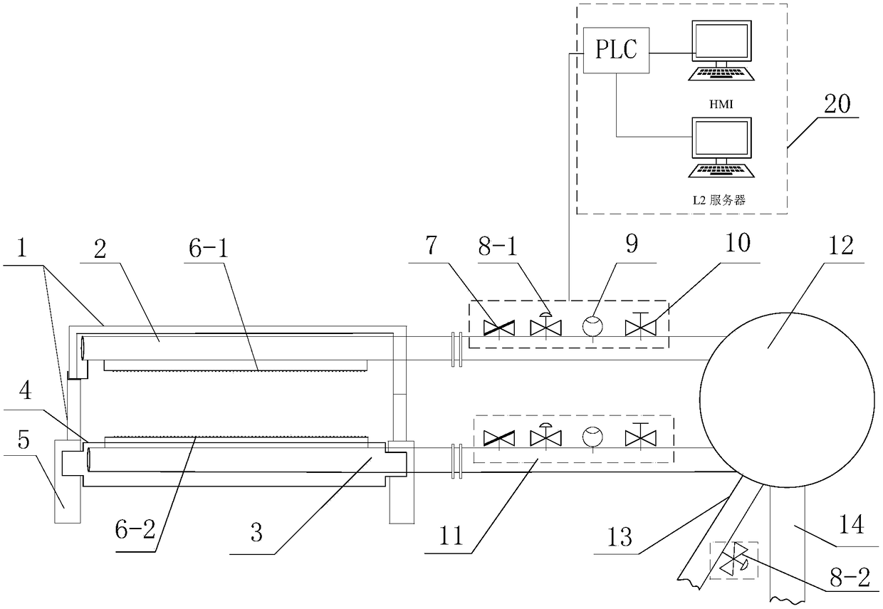
[0046] A hot continuous rolling intermediate billet cooling device, its structure schematic diagram is shown in figure 1 , specifically including the rapid cooling system of the intermediate billet, the water supply system and the automatic control system;

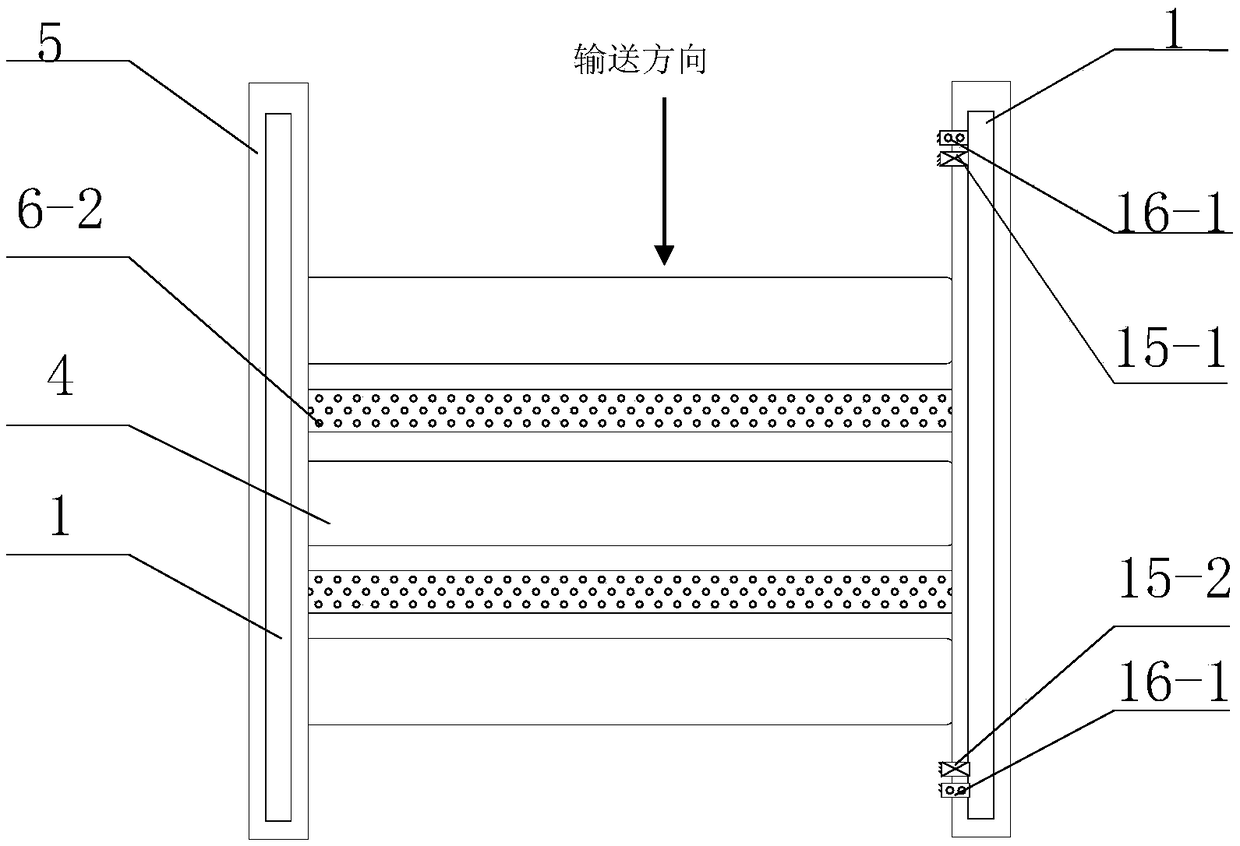
[0047] The intermediate billet rapid cooling system is arranged at the hot continuous rolling conveying roller table, figure 1 The installation direction of the device is perpendicular to the conveying direction of the hot continuous rolling conveying roller table. The rapid cooling system of the intermediate billet includes the equipment main frame 1, the upper header 2, the lower header 3, the air spray device and the high-pressure side spray device, specifically :

[0048] The main body frame 1 of the equipment is arranged at the hot continuous rolling conveying roller table, and is connected with the hot continuous rolling roller table frame 5;

[0049] The upper header 2 is arranged above the hot continuous rolling ...

Embodiment 2

[0064] A hot continuous rolling intermediate slab cooling device, same as embodiment 1.

[0065] A method for using a hot continuous rolling intermediate slab cooling device, using such as Figure 4 The arrangement method shown includes the following steps:

[0066] The hot continuous rolling intermediate billet cooling device adopts the second process arrangement method, that is, the hot continuous rolling intermediate billet cooling device 17 is arranged between the rough rolling mill and the finishing mill, close to the finishing mill side, 35m away from the center line of the first finishing stand, and the hot rolling mill Continuous rolling intermediate slab cooling device, including 4 pairs of cooling headers.

[0067] In this embodiment, the cooling water pressure is controlled at 0.8 MPa, and the water volume of a single header is 220-320 m3 / h. Taking the production of X70 pipeline steel with a thickness of 22mm as an example, after rough rolling R2, the thickness of...

Embodiment 3

[0069] A hot continuous rolling intermediate slab cooling device, same as embodiment 1.

[0070] A method for using a hot continuous rolling intermediate slab cooling device, using such as Figure 5 The arrangement method shown includes the following steps:

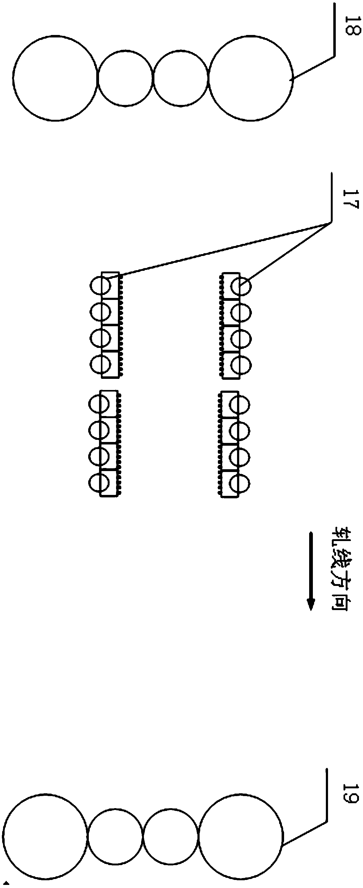
[0071] The hot continuous rolling intermediate billet cooling device adopts the third process layout method. The hot continuous rolling intermediate billet cooling device 17 is arranged at the entrance and exit of the rough rolling R2 stand 18, and the hot continuous rolling intermediate billet cooling device 17 is 5m away from the center line of the roughing mill. , The hot continuous rolling intermediate billet cooling device 17 arranged at the entrance of the rough rolling mill includes 2 pairs of cooling headers, and the hot continuous rolling intermediate billet cooling device 17 arranged at the exit of the rough rolling mill includes 2 pairs of cooling headers. The cooling water pressure is controlled at 0.8MPa, an...


PUM

PropertyMeasurementUnit
thicknessaaaaaaaaaa
thicknessaaaaaaaaaa
yield strengthaaaaaaaaaa

Abstract

The invention discloses a cooling device of a hot continuous rolling intermediate billet and a using method thereof, and belongs to the field of hot continuous rolling plate strip steel control cooling. The cooling device comprises an intermediate billet rapid cooling system, a water supply system and an automatic control system; the intermediate billet rapid cooling system is arranged at the rollgang position of the hot continuous rolling, and upper header of the intermediate billet rapid cooling system is arranged above a rollgang of the hot continuous rolling; lower header of the intermediate billet rapid cooling system is arranged on the rollgang of the hot continuous rolling and is arranged between every adjacent conveying rolls at intervals; and the upper / lower header are connected to one end of a water pipe of a water supply pipeline, and a flow guiding collector pipe is connected to the other end of the water pipe of the water supply pipeline. The using method of the cooling device is divided into (1) being arranged between rough rolling and finish rolling (2) being arranged on the side close to finish rolling; and (3) being arranged near both sides of rough rolling according to the arrangement form of the device. According to the using method, the problem that the rolling efficiency is reduced due to air cooling and temperature waiting of the intermediate billet is solved; and meanwhile, diversified process requirements such as differential temperature rolling and controlled rolling coupled with rolling and water cooling are met through efficient and flexible control over the temperature of the intermediate billet.

Description

technical field [0001] The invention relates to the technical field of controlled cooling of hot continuous rolling strip steel, in particular to a hot continuous rolling intermediate billet cooling device and a method for using the same. Background technique [0002] The hot-rolled plate and strip steel production line rolls high-strength steel and products that require controlled rolling, such as rolling in the ferrite zone, etc., which are limited by the finishing rolling temperature (FET), and need to be air-cooled and warm-rolled in the rough rolling zone to meet The temperature requirements for finishing rolling. However, the problem brought about by air cooling and waiting for temperature is that the rolling production rhythm of the rolling line is greatly reduced, and the production capacity is significantly reduced, which seriously restricts the production capacity of the rolling line. At the same time, the austenite grains will coarsen during the long-time heating...

Claims


Application Information

Patent Timeline
Patent Type & Authority Applications(China)
IPC IPC(8): B21B45/02B21B37/74
CPCB21B37/74B21B45/0233Y02P70/10
Inventor 袁国李振垒康健陈冬汤洋王黎筠王国栋
Owner NORTHEASTERN UNIV
Why Eureka
Try Eureka